9
Program
9.2.2. Detailed Description of the Function
The following explains the details on reading "Direct I/O and electromagnetic brake status"
(register address: #00D4) by using the function "Reading from a holding register(s) (function
code: #03)".
For details on register addresses, refer to Register address list in Method of control via
Modbus RTU(RS-485 communication) of the Brushless Motor and Driver Package BLE
Series FLEX RS-485 communication type USER MANUAL (HM-5140).
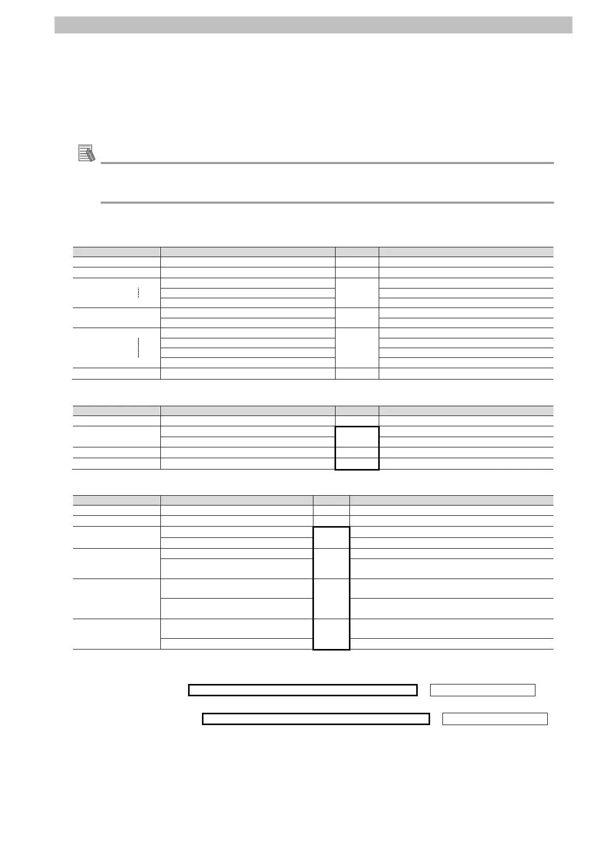
●CMND instruction operands
・Setting contents of the first control word (C: CIO 5010)
Number of command data bytes (4-digit hex)
+
Number of response data bytes (4-digit hex)
11 bytes from D to the leftmost byte of D+5
C+2
#0000
Serial port number (1-digit hex)
Destination network address (2-digit hex)
C+3
Destination node address (2-digit hex)
#0080
Destination unit address (2-digit hex)
C+4
Response needed/not needed (1-digit hex)
#0703
Logical port number (1-digit hex)
Resend times (1-digit hex)
+
Response timeout (4-digit hex)
・Setting contents of the first command word (S: CIO 5020)
Command code (4-digit hex)
S+1
Slave address (2-digit hex)
#0103
#01: Destination Device address
Function code (2-digit hex)
#03: Reading from a holding register(s)
+
Register address (4-digit hex)
Direct I/O and electromagnetic brake status
+
Number of read words (4-digit hex)
・Storing contents of the first response word (D: CIO 5500)
Command code (4-digit hex)
+
****
D+2
Slave address (2-digit hex)
#0103
#01: Slave address in S+1
Function code (2-digit hex)
#03: Function code in S+1
D+3
Number of bytes to read (2-digit hex)
#04**
#04: Twice the number of read words S+3
Lower Read data (first byte)
The first byte of Direct I/O and electromagnetic brake
status
D+4
Upper Read data (second byte)
#****
The second byte of Direct I/O and electromagnetic
brake status
Lower Read data (third byte)
The third byte of Direct I/O and electromagnetic
brake status
D+5
Upper Read data (forth byte)
#**00
The forth byte of Direct I/O and electromagnetic
brake status
●Send/Receive messages
・Send message Command data surrounded by bold lines above + CRC16 data (2 bytes)
・Receive message Response data surrounded by bold lines above + CRC16 data (2 bytes)
*CRC16: Error check code of send/receive data (When sending the data, the error check code
is automatically added in the send data by Modbus-RTU command. After the error
check code is automatically checked when receiving the data, the error check code
is deleted from the receive data.)