3-1
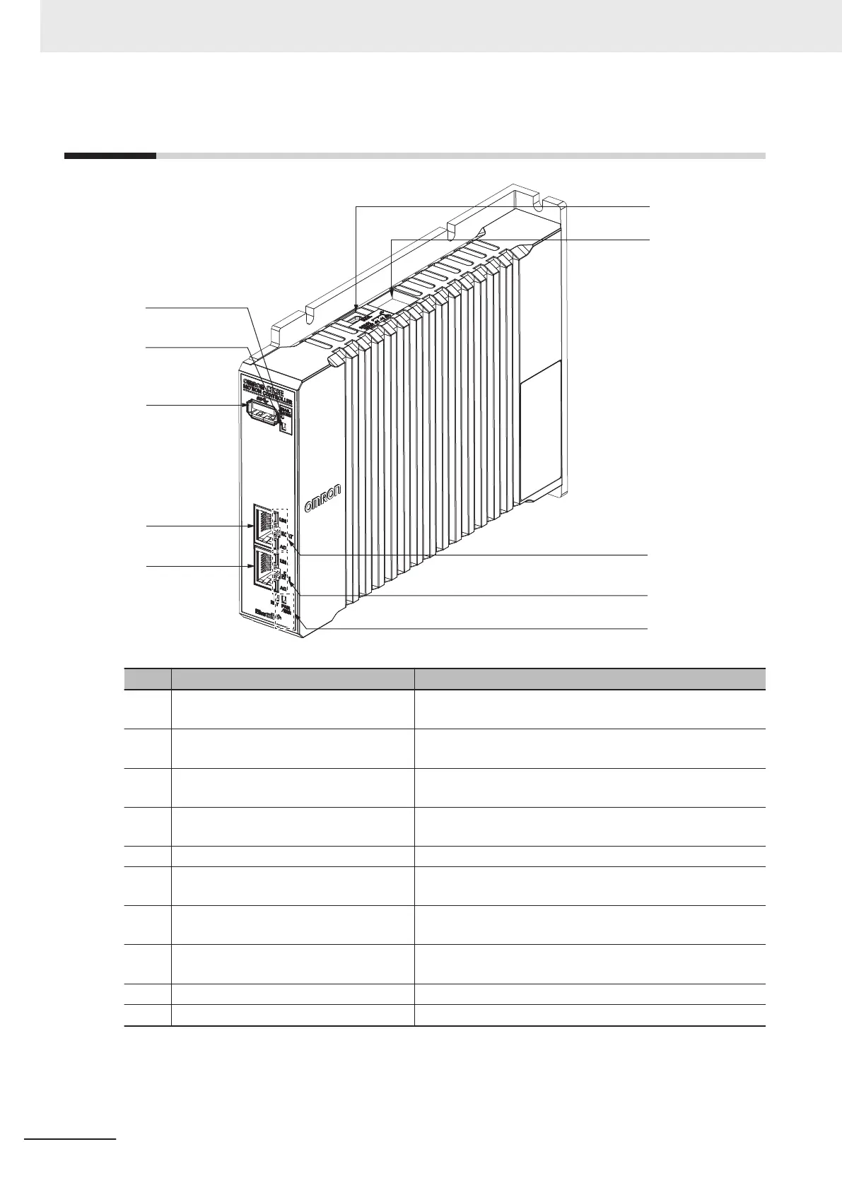
Part Names and Functions
(A)
(B)
(C)
(D)
(E)
(F)
(G)
(H)
(J)
(I)
Letter Name Function
(A) USB 3.0 connector The connector of USB 3.0 interface.
Used to connect a USB memory device.
(B) Maintenance mode LED Not used.
Used for maintenance.
(C) Maintenance mode enter button Not used.
Used to enter Maintenance mode. The user does not use it.
(D) USB 2.0 connector Not used.
Used for maintenance. The user does not use it.
(E) Power supply connector Connects to the Unit power supply.
(F) EtherCAT communications port opera-
tion indicators
Shows the operation status of EtherCAT.
(G) Ethernet communications port operation
indicators
Shows the operation status of Ethernet.
(H) Unit operation indicators. Shows the operation status of the Unit using multiple indica-
tors.
(I) Ethernet communications connector Connects to an Ethernet network communications cable.
(J) EtherCAT communications connector Connects to an EtherCAT network communications cable.
3 Part Names and Functions
3-2
CK3E-series Programmable Multi-Axis Controller User’s Manual Hardware (I610)
 Loading...


