5-2
Using the Indicators to Check Errors
5-2-1
Indicator Types
The following shows the indicators on the Motion Controller and their functions.
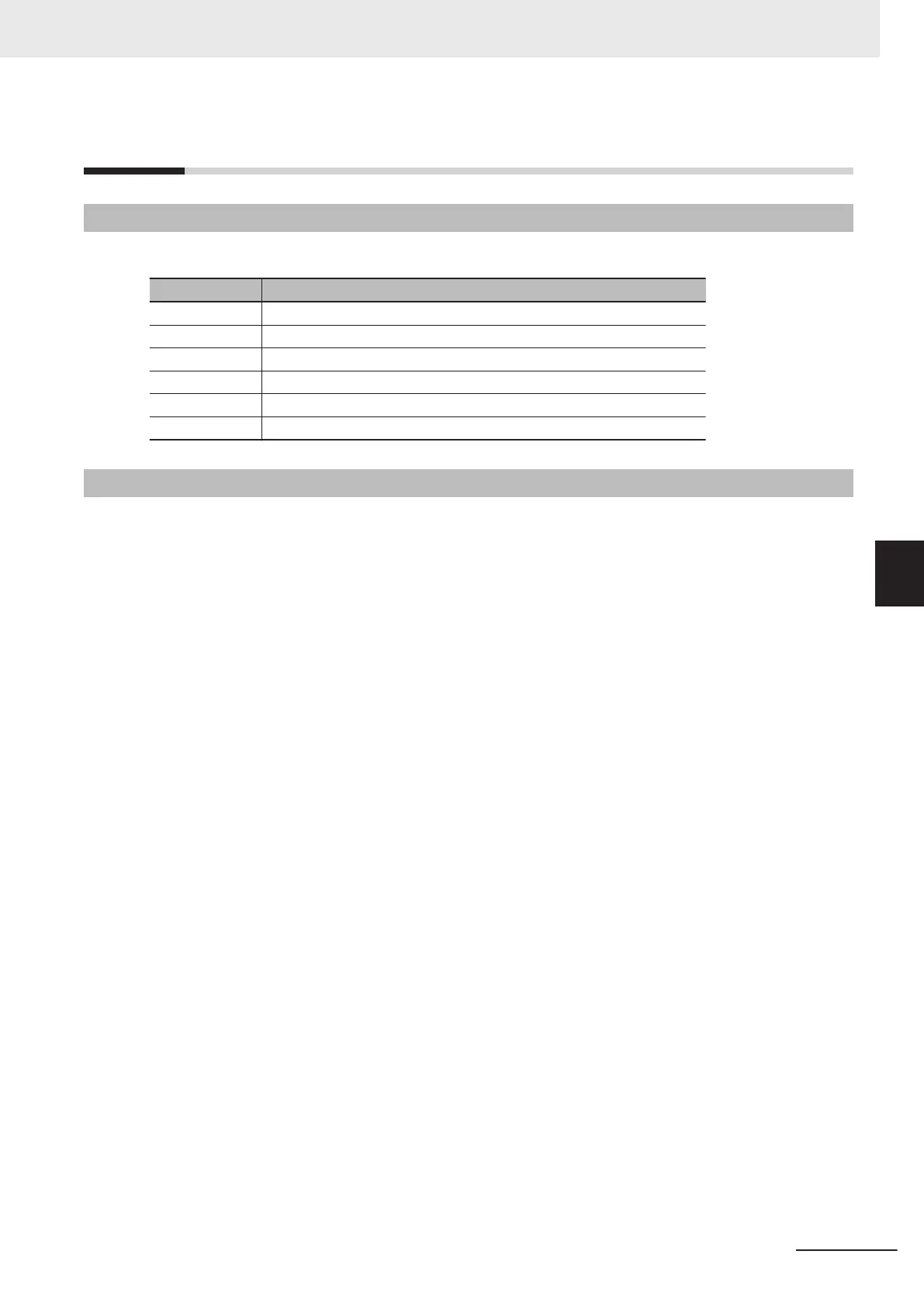
Indicator name Function
ECAT LINK Shows the link status of EtherCAT communications.
ECAT ACT Shows the data communications status of EtherCAT communications.
Ethernet LINK Shows the link status of Ethernet communications.
Ethernet ACT Shows the data communications status of Ethernet communications.
PWR/ERR Shows the power supply status to the Unit and the error status.
RDY Shows whether the Unit is in operation-ready status.
5-2-2
Procedure for Determining Errors
When an error occurs in the Motion Controller, use the following flowchart to check the indicators and
determine whether "the error is “fatal” for the Motion Controller
" or "the error is “non-fatal” for the
Motion Controller".
5 Error Processing
5-3
CK3E-series Programmable Multi-Axis Controller User’s Manual Hardware (I610)
5-2 Using the Indicators to Check Errors
5
5-2-1 Indicator Types
 Loading...


