66
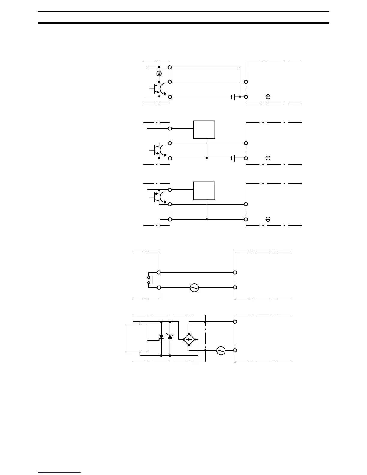
Sensor Inputs When using the following configurations, the sensor and Input Unit should re-
ceive their power from the same source.
+
COM
NPN
current output
IN
DC input
0 V
Output
7 mA
Current
regulator
+
COM
NPN open-collector output
Sensor
Power
Supply
IN
DC input
0 V
Output
7 mA
+
COM
PNP current output
Sensor
Power
Supply
IN
AC/DC input
0 V
Output
7 mA
AC Inputs
COM
Contact
output
IN
AC input
COM
AC Switching
IN
AC input
Prox.
switch
main
circuit
3-6 Compliance with EC Directives
The
following precautions must be abided by when installing CV
-series PCs to
meet EC Directives.
1, 2, 3...
1. CV-series PCs are classified as open-structure devices and must be
installed inside a control panel.
2. Use
reinforced insulation or double insulation on the DC power supply con
-
nected to CV500-PS211 Power Supply Unit and DC I/O Units.
3. Use separate power supplies for Relay Output Units and DC I/O Units.
Compliance with EC Directives Section 3-6

 Loading...


