7 - 17
7 User Calibration
E5@C Digital Temperature Controllers User’s Manual (H174)
7-7 Checking Indication Accuracy
7
Analog Input
• Preparations
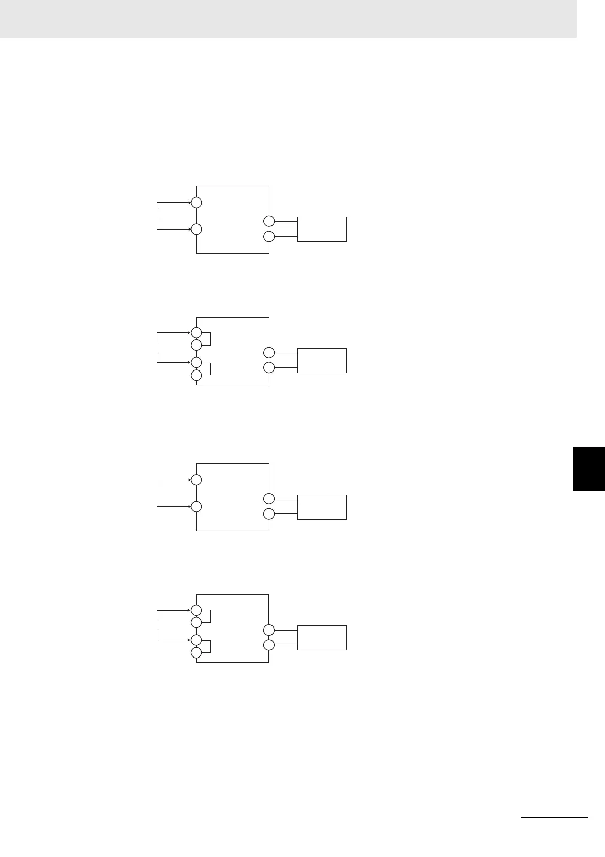
The diagram below shows the required device connections.
(The connection terminals depend on the model and input type.)
Current Input
Voltage Input
• Operation
Set the STV output to the voltage or current test value.
Input power supply
Input power supply
+
−
STV
−
STV
+
E5CC-B or E5EC-B
E5CC, E5CC-U, E5EC, E5AC, E5DC, E5DC-B, or E5GC
*
*
* Common terminals are indicated with asterisks (*).
C
D
C
C'
D
D'
The terminal numbers are
as follows:
• Input Terminals
(Positive and Negative)
E5CC: 4 and 5
E5CC-U: 3 and 2
E5EC/E5AC: 22 and 23
E5DC: 12 and 13
E5DC-B: 11 and 15
E5GC: 10 and 11
• Input Power Supply
(C/D)
E5CC: 11 and 12
E5CC-U: 10 and 11
E5EC/E5AC: 1 and 2
E5DC: 1 and 2
E5DC-B: 1 and 2
E5GC: 1 and 2
The terminal numbers are as follows:
• Input Terminals (Positive and Negative)
E5CC-B: 6 and 7
E5EC-B: 30 and 31
• Input Power Supply (C or C', and D or D')
E5CC-B: 13 or 14, and 15 or 16
E5EC-B: 1 or 2, and 3 or 4
−
+
+
STV
STV
E5CC-B/E5EC-B
E5CC, E5CC-U, E5EC, E5AC, E5DC, E5DC-B, or E5GC
*
*
* Common terminals are indicated with asterisks (*).
C
D
C
C'
D
D'
−
Input power supply
Input power supply
The terminal numbers are
as follows:
• Input Terminals (Negative
and Positive)
E5CC: 5 and 6
E5CC-U: 2 and 1
E5EC/E5AC: 23 and 24
E5DC: 13 and 14
E5DC-B: 15 and 16
E5GC: 11 and 12
• Input Power
Supply (C/D)
E5CC: 11 and 12
E5CC-U: 10 and 11
E5EC/E5AC: 1 and 2
E5DC: 1 and 2
E5DC-B: 1 and 2
E5GC: 1 and 2
The terminal numbers are as follows:
• Input Terminals (Negative and Positive)
E5CC-B: 7 and 8
E5EC-B: 31 and 32
• Input Power Supply (C or C', and D or D')
E5CC-B: 13 or 14, and 15 or 16
E5EC-B: 1 or 2, and 3 or 4
 Loading...


