E5CS-X
E5CS-X
12
Precautions
Mounting
All Temperature Controllers in the E5CS-X Series conform to
DIN43700
standard.
The recommended panel thickness is 1 to 4 mm.
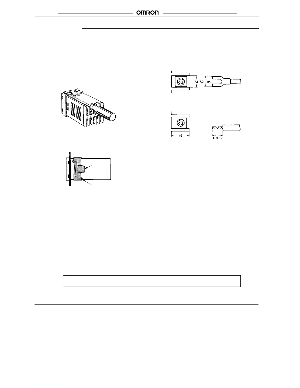
Flush Mounting
Insert
the T
emperature Controller
, back end first,
into the hole of the
mounting panel. Mount the adapter by pushing it forward from the
back of the Temperature Controller. Push the adapter as close as
possible
to the front panel of
the T
emperature Controller to eliminate
the gap between them. Then, secure the adapter with screws as
shown
in the figure below
.
Removal
Loosen the screws on the adapter and push the hook open to re-
move
the adapter
.
Hook
Screw
Environment
Do
not install the T
emperature Controller
in locations subject to dust
or
corrosive gases. Do not install the T
emperature Controller in loca
-
tions
subject to heavy vibrations or shocks, splashes of water or oil,
or
high temperatures.
Separate the Temperature Controller from equipment that gener-
ates
strong, high-frequency noise such as high-frequency welders.
Connection Examples
Solderless
T
erminal
Use M3.5 solderless terminals with the Temperature Controller’s
M3.5 self-rising pressure plate screws.
Solder-dipped Lead W
ires
Strip the lead wire 6 to 12 mm and carefully arrange the wire tip.
Do not tighten the terminal screw with excessive force.
Input Sensor Connection
The
lead wires connecting the sensor to the T
emperature
Controller
must be separated from
power lines and load lines wherever pos
-
sible, to prevent them from being induced by noise.
Use the specified compensating conductors for the thermocouple
type
T
emperature Controllers.
Use lead wires with
a small resistance for the Platinum resistance
thermometer type Temperature Controllers.
Sequence Circuit
Several
seconds are required until the relay is turned ON after pow
-
er is supplied to the Temperature Controller. Therefore, take this
time
lag into consideration when designing a sequence circuit which
incorporates
the T
emperature Controller
.
OMRON Corporation
Industrial
Automation Company
Measuring and Supervisory Controls Division
28th Fl., Crystal T
ower Bldg.,
1-2-27, Shiromi, Chuo-ku,
Osaka 540-6028 Japan
T
el: (81)6-6949-6035/Fax: (81)6-6949-606
ALL DIMENSIONS SHOWN ARE IN MILLIMETERS.
To
convert millimeters into inches, multiply by 0.03937. T
o convert grams into ounces, multiply by 0.03527.
Cat. No. H032-E1-2A In the interest of product improvement, specifications are subject to change without notice.
Printed
in Japan
0300-0.3M (0689)
a
 Loading...


