E5CS-X
E5CS-X
6
Operation
T
emperature Setting
Press
the temperature indication switching key until the SP indicator
lights. Then set the desired temperature value using the upward and
downward setting keys.
Alarm Setting
Press
the temperature indication switching key until the AL indicator
lights. Then set the desired alarm value in units of °C or °F. If the
present
temperature reaches the set alarm value,
alarm output will
be
enabled.
Sensor Failure
The
error message “FFF” or “– – –” will appear on the main display if
the
temperature sensor
, such as the thermocouple or platinum
re
-
sistance
thermometer
,
short-circuits or breaks. (Refer to
Error Mes
-
sages
for details of the messages displayed.)
Note: Neither
the set alarm value is displayed nor
the AL indicator
lights
with
the internal alarm mode selector switch set to 0
or
9. The alarm mode selector switch is provided inside the
housing,
and is positioned dif
ferently on each model.
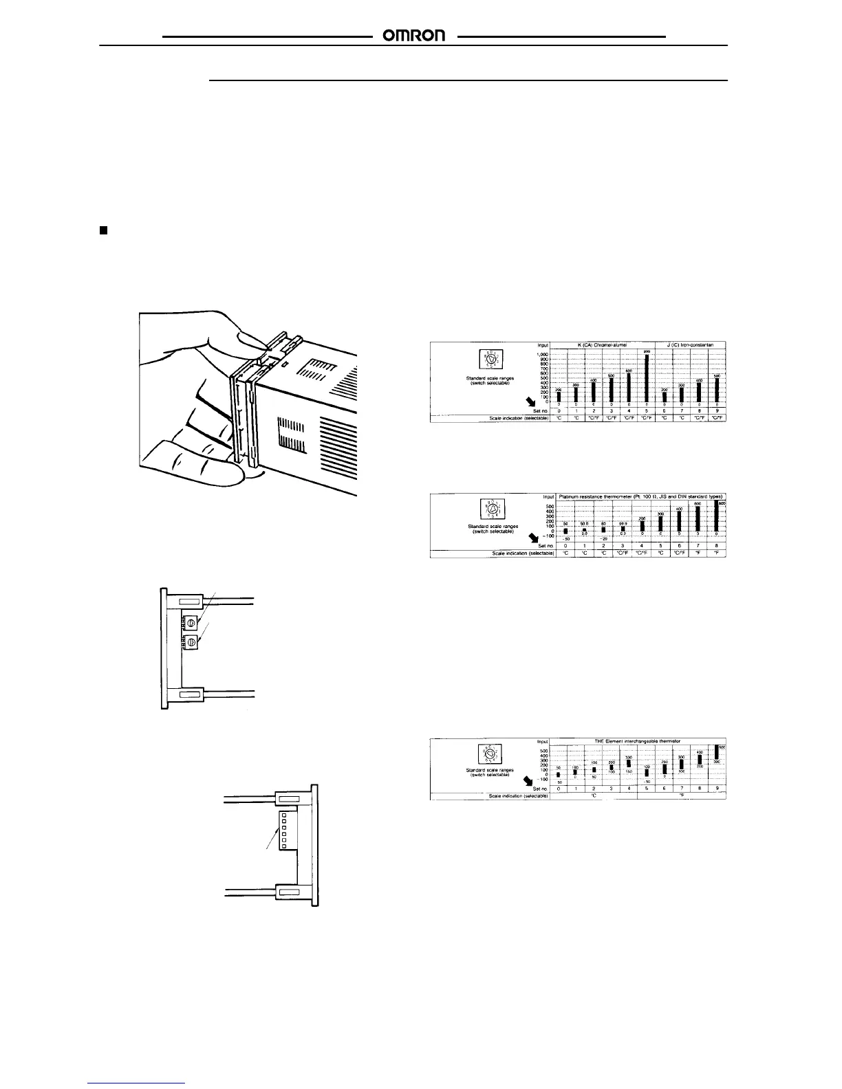
Function Setting
The various functions of the Temperature Controller are set using
the switches on the internal mechanism. To gain access to these
switches,
the internal mechanism must be first drawn out from the
housing.
Push the tab on the underside of the housing, and pull out
the
mechanism.
Select
the desired temperature range using the temperature range
selector switch (rotary DIP type). Eight or nine temperature ranges
can
be selected depending on the model.
The set temperature is automatically changed when the tempera-
ture
range is changed. Be sure to confirm the set temperature.
Temperature range selector switch
Alarm mode selector switch
Right side view
T
emperature unit (C
°
or F
°),
where a choice is available, is selected
using
pin 6 of the internal DIP switch
which is also used for other set
-
tings,
such as the control mode and sensor compensation.
Internal DIP switch
Left side view
The procedures for making actual settings are given below
.
Setting the Temperature Range
Set
the desired temperature range by using the temperature range
selector
switch (“Set no.” setting in the tables below). Eight or nine
temperature
ranges can be selected depending on the model.
Thermocouple T
ype
The
display can indicate temperatures 10% beyond each of the set
ranges.
Platinum
Resistance Thermometer T
ype
Do
not set the selector switch to “9.” Doing so will result in the error
message
“FFF” or “– – –” being displayed.
Note: 1. The
unit in which the temperature can be set is multiplied
by
10 when the temperature range is changed from 0.0
to
50.0 or 0.0 to 99.9 to a range in which the temperature
can be set in 1° units. Conversely, if the temperature
range
is changed from one in which
the temperature can
be
set in
1
°
units to a range of 0.0 to 50.0 or 0.0 to 99.9,
the
unit is decreased to 1/10 of the original unit.
2. The display can indicate temperatures 10% beyond
each
of the set ranges.
Thermistor T
ype
Note: 1. The
temperature range selector switch
is factory-set to
“0.” With a temperature range, such as 50° to 150°C,
that
exceeds the setting range, the indication unit is au
-
tomatically
adjusted to the minimum value. The set
tem
-
perature
is displayed when power is turned ON.
2. The
temperature range that can actually be indicated
for
a
set temperature range of –50
°
to 50
°
C is
–50
°
to 60
°C.
For other temperature range settings it is the full scale
±10%.
 Loading...


