E5CSL/E5CWL/E5EWL
4
Characteristics
Note: 1. The indication accuracy of K and T thermocouples at a temperature of −100°C max. is ±2°C ±1 digit maximum. The indication accuracy
of the R and S thermocouples at a temperature of 200°C max. is ±3°C ±1 digit max.
2. R, and S sensors: 0.2°C/Ω max. (100 Ω max.)
3. Industrial electromagnetic environment (EN/IEC 61326-1 Table 2)
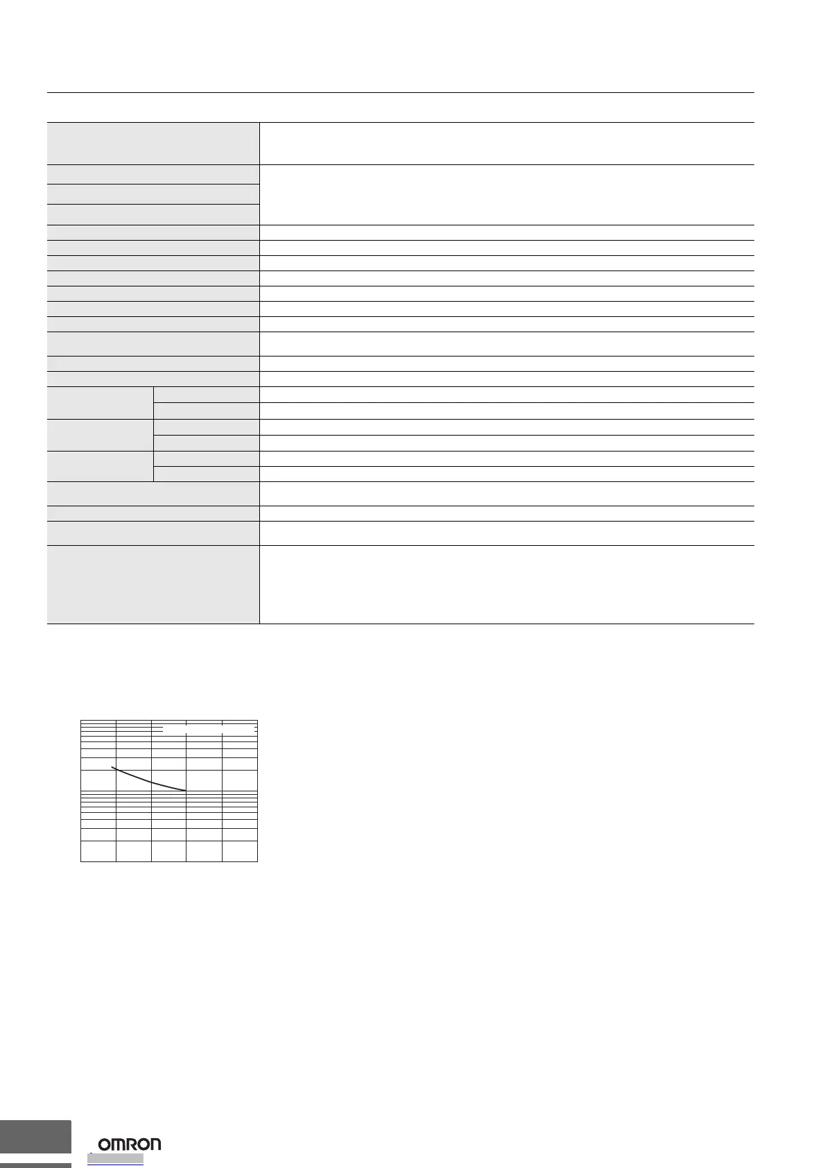
Electrical Life Expectancy Curve for Relays (Reference Values)
Indication accuracy
Thermocouple: (See note 1.)
(±0.5% of indicated value or ±1°C, whichever is greater) ±1 digit max.
Platinum resistance thermometer:
(±0.5% of indicated value or ±1°C, whichever is greater) ±1 digit max.
Influence of temperature
R and S thermocouple inputs:
(±1% of PV or ±10°C, whichever is greater) ±1 digit max.
K, J, and T thermocouple inputs:
(±1% of PV or ±4°C, whichever is greater) ±1 digit max.
Platinum resistance thermometer inputs:
(±1% of PV or ±2°C, whichever is greater) ±1 digit max.
Influence of voltage
Influence of EMS. (at EN61326-1)
Hysteresis 0.1 to 999.9 (in units of 0.1) °C/°F
Proportional band (P) 0.1 to 999.9 (in units of 0.1) °C/°F
Integral time (I) 0 to 3999 s (in units of 1 s)
Derivative time (D) 0 to 3999 s (in units of 1 s)
Control period 0.5, 1 to 99 s (in units of 1 s)
Alarm setting range −1999 to 9999 (decimal point position depends on input type)
Sampling period 250 ms
Affect of signal source resistance
Thermocouple: 0.1°C/Ω max. (100 Ω max.) (See note 2.)
Platinum resistance thermometer: 0.6°C/Ω max. (10 Ω max.)
Insulation resistance 20 MΩ min. (at 500 VDC)
Dielectric strength 2,300 VAC, 50 or 60 Hz for 1 min (between terminals with different charge)
Vibration resistance
Malfunction
10 to 55 Hz, 20 m/s
2
for 10 min each in X, Y, and Z directions
Destruction
10 to 55 Hz, 20 m/s
2
for 2 hrs each in X, Y, and Z directions
Shock
resistance
Malfunction
100 m/s
2
min., 3 times each in X, Y, and Z directions
Destruction
300 m/s
2
min., 3 times each in X, Y, and Z directions
Weight
E5CSL/E5CWL Controller: Approx. 100 g, Mounting Bracket: Approx. 10 g
E5EWL Controller: Approx. 150 g, Mounting Bracket: Approx. 10 g
Degree of protection
Front panel: IP50
Rear case: IP20, Terminals: IP00
Memory protection Non-volatile memory (number of writes: 100,000 times)
Conformed standards
EN61326-1 (See note 3.), EN61010-1, IEC61010-1
VDE0106 Part 100 (Finger protection), when the terminal cover is mounted.
EMC
Emission Enclosure: EN55011 Group1 Class A
Emission AC Mains: EN55011 Group1 Class A
Immunity ESD: EN61000-4-2
Immunity RF-interference: EN61000-4-3 10 V/m
Immunity Conducted Disturbance: EN61000-4-6 3 V
Immunity Burst: EN61000-4-4
Immunity Surge: EN61000-4-5
Immunity Voltage Dip/Interrupting: EN61000-4-11
Contact current (A)
250 VAC, 30 VDC resistive load
No. of operations (x 10
4
)
100
50
30
10
5
3
1
012 34 5
Downloaded from Arrow.com.Downloaded from Arrow.com.Downloaded from Arrow.com.Downloaded from Arrow.com.

 Loading...