E5CSL/E5CWL/E5EWL
5
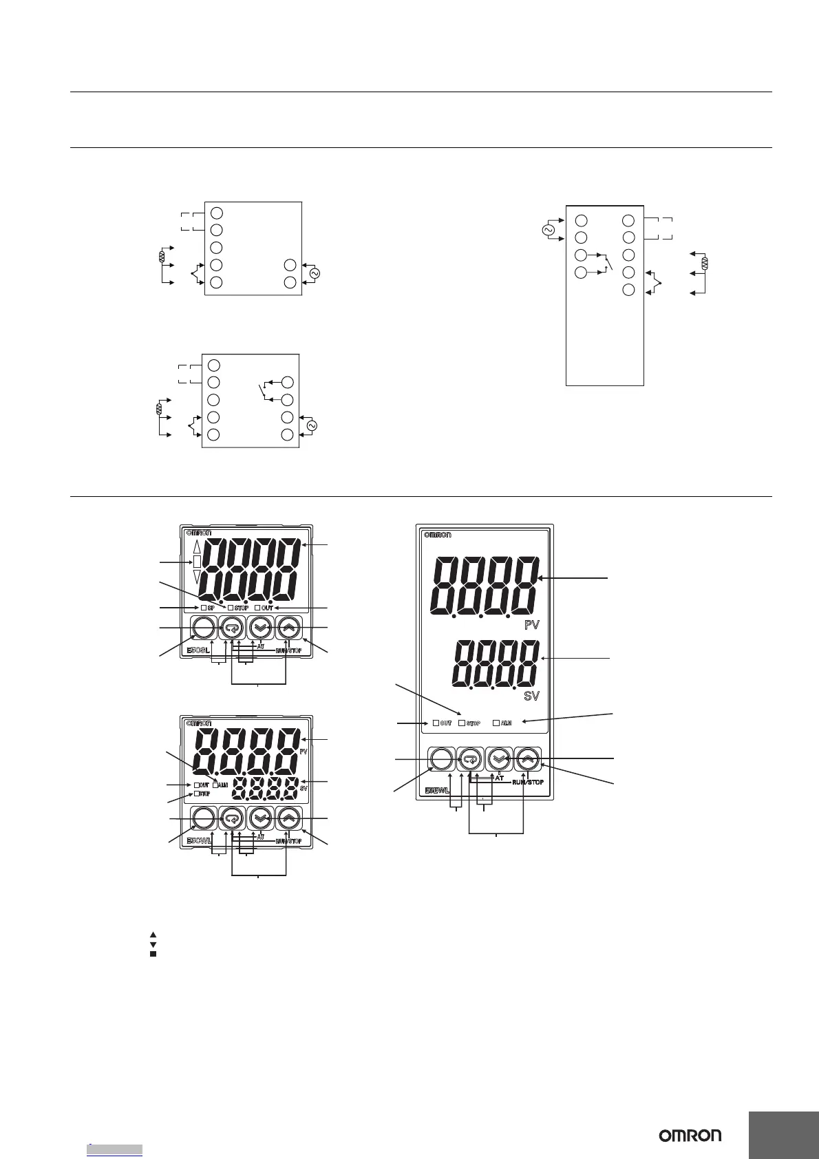
External Connections
A voltage output (control output) is not electrically insulated from the internal circuits. When using a grounding thermocouple, do not connect
any of the control output terminals to ground. If the control output terminals are connected to ground, errors will occur in the measured
temperature values as a result of leakage current.
Nomenclature
E5CSL E5EWL
+
−
A
B
B
Pt input
Input power supply:
100 to 240 VAC,
50/60 Hz
DO NOT
USE
Control output
+
−
TC input
1
Control Output
• Relay output: 250 VAC, 3 A (resistive load)
• Voltage output (for driving SSR): 12 VDC, 21 mA
2
3
4
5
9
10
Input power supply:
100 to 240 VAC,
50/60 Hz
Control Output
• Relay output: 250 VAC, 3 A (resistive load)
• Voltage output (for driving SSR): 12 VDC, 21 mA
Pt input
Alarm Output
• Relay output: 250 VAC, 1 A
(resistive load)
DO NOT USE
TC input
+
−
A
B
B
+
−
1
2
3
4
7
8
9
10
6
Control output
+
−
A
B
B
Pt input
Alarm Output
• Relay output: 250 VAC, 1 A
(resistive load)
Input power supply:
100 to 240 VAC,
50/60 Hz
DO NOT
USE
Control output
+
−
TC input
1
Control Output
• Relay output: 250 VAC, 3 A (resistive load)
• Voltage output (for driving SSR): 12 VDC, 21 mA
2
3
4
5
7
8
9
10
(10)
D
Down Key: Reduces the setting.
(11)
U
Up Key: Increases the setting.
(12)
O
+
M
Press these keys for at least 3 seconds in Operation Level or Adjustment Level to go to Protect Level.
Press these keys for at least 1 second in Protect Level to return to Operation Level.
(13)
M
+
D
Press these keys for at least 2 seconds to start or stop autotuning.*1
(14)
M
+
U
Press these keys for at least 2 seconds to start or stop operation.*2
(3)
(7)
(4)
(9)
(8)
(12) (13)
(14)
(11)
(10)
(6)
(1)
(12)
(13)
(14)
(11)
(10)
(2)
(1)
(6)
(7)
(8)
(5)
(9)
*1: These keys are disabled when starting and stopping autotuning has been disabled with operation control
key protection.
*2: These keys are disabled when starting and stopping operation has been disabled with operation control
key protection.
(1) Display No. 1
Displays the process value (PV) or parameter. For the E5CSL/E5EWL,
the set point or parameter setting is also displayed.
(2) Display No. 2 Displays the set point (SP) or parameter setting.
(3) Deviation Show the relation between the process value and the set point.
Indicators Lit: The process value is more than 5°C/°F higher than the set point.
Lit: The process value is more than 5°C/°F lower than the set point.
Lit: The process value is within 5°C/°F of the set point.
The relevant deviation indicator will flash during autotuning.
(4) SP Lit while the set point is displayed on display No. 1 (E5CSL only).
(5) ALM Lit while the alarm is ON. Not lit while the alarm is OFF.
(6) OUT Lit while the control output is ON. Not lit while the control output is
OFF.
(7) STOP Not lit during operation. Lit while operation is stopped.
(8)
O
Level Key: Changes the setting level.
(9)
M
Mode Key: Changes the parameter within the setting level.
(14)
(13)(12)
(5)
(2)
(1)
(10)
(11)
(7)
(6)
(9)
(8)
Downloaded from Arrow.com.Downloaded from Arrow.com.Downloaded from Arrow.com.Downloaded from Arrow.com.Downloaded from Arrow.com.

 Loading...