EasyManua.ls Logo

Omron H3DE-M1 User Manual

Omron H3DE-M1
14 pages
To Next Page IconTo Next Page
Page #1 background image
Multifunction Timer H3DE
Analog Set Multifunction Timers
In Slim 22.5 mm Design
For Track Mounting
H
Wide AC/DC power supply range
(24 to 230 VAC/DC) minimizes inventory
H
12 VDC available in H3DE-M model
H
Programmable contacts (available in
-M2 and -S2 m odels) can enable and
disable a self -holding relay circuit
H
Eight operating modes in the H3DE-M
(four in the H3DE-S) offer wide
application flexibility
H
Time setting range 0.10 sec to 120 hrs
H
Finger protection terminal block
Ordering Information
J TIMER
Description Part number
Contact output Supply voltage Multifunctional Standard
DPDT (time-limit output SPDT);
and switchable SPDT
(
t
i
m
e
-
l
i
m
i
t
i
n
s
t
a
n
t
a
n
e
o
u
s
)
12 VDC H3DE-M2 DC12
(
t
i
me-
l
i
m
i
t
←→
i
ns
t
an
t
aneous
)
24 to 230
VAC/DC
H3DE-M2 AC/DC24-230 H3DE-S2 AC/DC24-230
SPDT (time-limit output SPDT) H3DE-M1 AC/DC24-230 H3DE-S1 AC/DC24-230
J MODEL NUMBER LEGEND
H3DE-j-j-j
123
1. M: Multifunction type
S: Standard type
2. 1: SPDT
2: DPDT
3. Supply voltage
J ACCESSORIES (ORDER SEPARATELY)
Item Description Part number
Mounting track 50 cm (l) x 7.3 mm (t) PFP-50N
1m(l)x7.3mm(t) PFP-100N
1 m (l) x 16 mm (t) PFP-100N2
End plate PFP-M
Spacer PFP-S
Question and Answer IconNeed help?

Do you have a question about the Omron H3DE-M1 and is the answer not in the manual?

Omron H3DE-M1 Specifications

General IconGeneral
BrandOmron
ModelH3DE-M1
CategoryTimer
LanguageEnglish

Summary

Ordering Information

Product Specifications

General Specifications

Provides overall product specifications including operating modes and terminal details.

Electrical Ratings

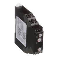
Outlines voltage, power consumption, and control output specifications.

Technical Characteristics

Product Nomenclature

Front Panel View

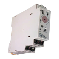
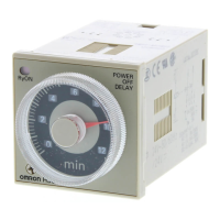
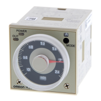
Identifies controls and indicators on the front of the timer.

Timer Operation

Functional Block Diagram

Illustrates the functional blocks for H3DE-M1/-M2 and H3DE-S1/-S2.

Basic Operation Guide

Selector Setting Procedures

Explains how to use selectors for time unit, scale, and mode.

Operating Mode Timing Charts

Provides timing diagrams for operating modes.

Installation Guide

Terminal Wiring Diagrams

Illustrates the terminal connections for H3DE-M1, M2, S1, and S2 models.

Power Supply Information

Input/Output Circuitry

Input/Power Supply Circuit Relationship

Explains the independent configuration of input and power supply circuits.

Related product manuals