H3DEH3DE
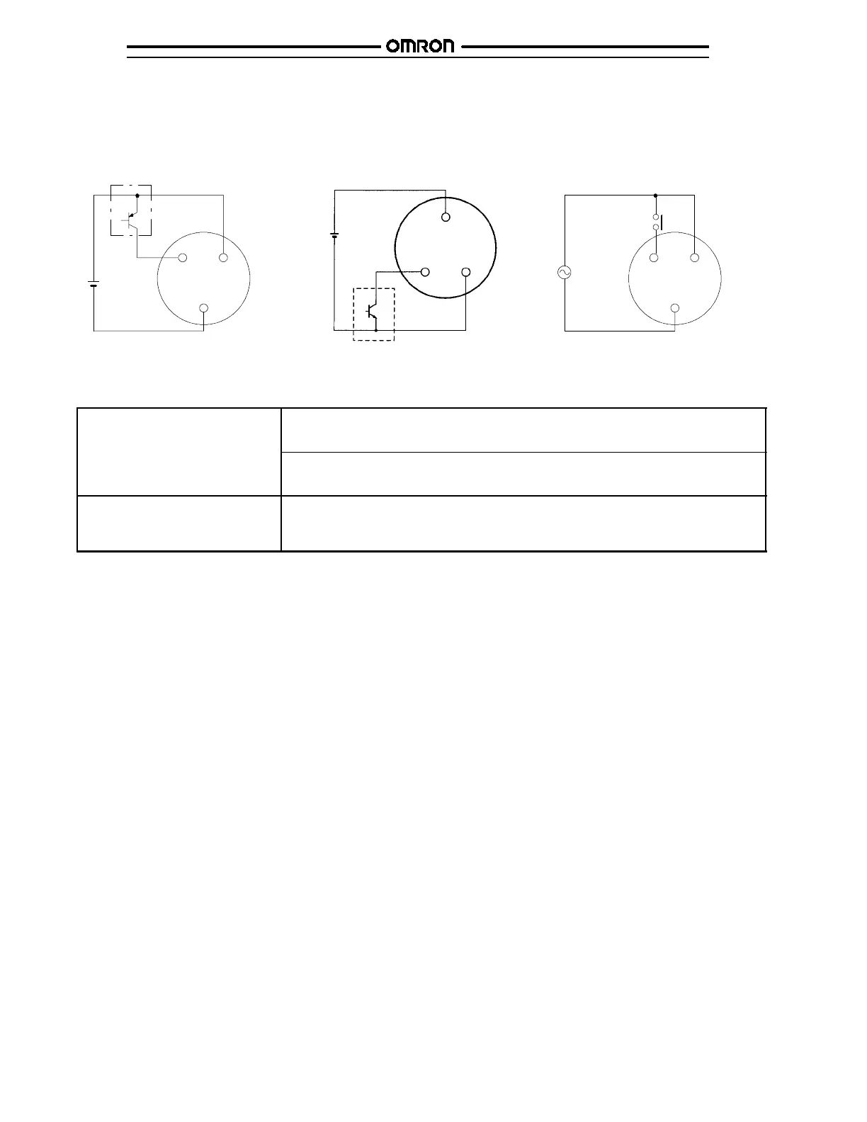
J INPUT CONNECTIONS
The inputs of the H3DE-M1/-M2 are voltage (voltage imposition or open) inputs.
No-Contact Input
Connection to PNP output sensor.
Contact Input
Sensor
A
1
B
1
Start
A
2
24 VDC
A
1
B
1
Start
A
2
Operates with PNP transi stor ON Operates with relay ON
TimerTimer
No-Contact Input
Connection to NPN output sensor.
(+)
(--)
Sensor
A
1
B
1
A
2
24 VDC
(+)
(--)
Operates with NP N transis tor ON
Timer
Voltage Input Signal Levels
No-contact input
1. Transistor ON
Residual voltage: 1 V max.; voltage between terminals B
1
and A
2
must be more than the rated
“H-level” voltage (20.4 VDC min.)
2. Transistor OFF
Leakage current: 0.01 mA max.; voltage between terminals B
1
and A
2
must be less than the
rated “L-level” voltage (2.4 VDC max.)
Contact input Use contacts that can adequately switch 0.1 mA at each voltage to be imposed. When the
contacts are ON or OFF, voltage between terminals B
1
and A
2
must be within the following
ranges. When contacts are ON: 20.4 to 253 VAC/DC. When contacts are OFF: 0 to 2.4
VAC/DC
 Loading...