5
H5CRH5CR
Operation
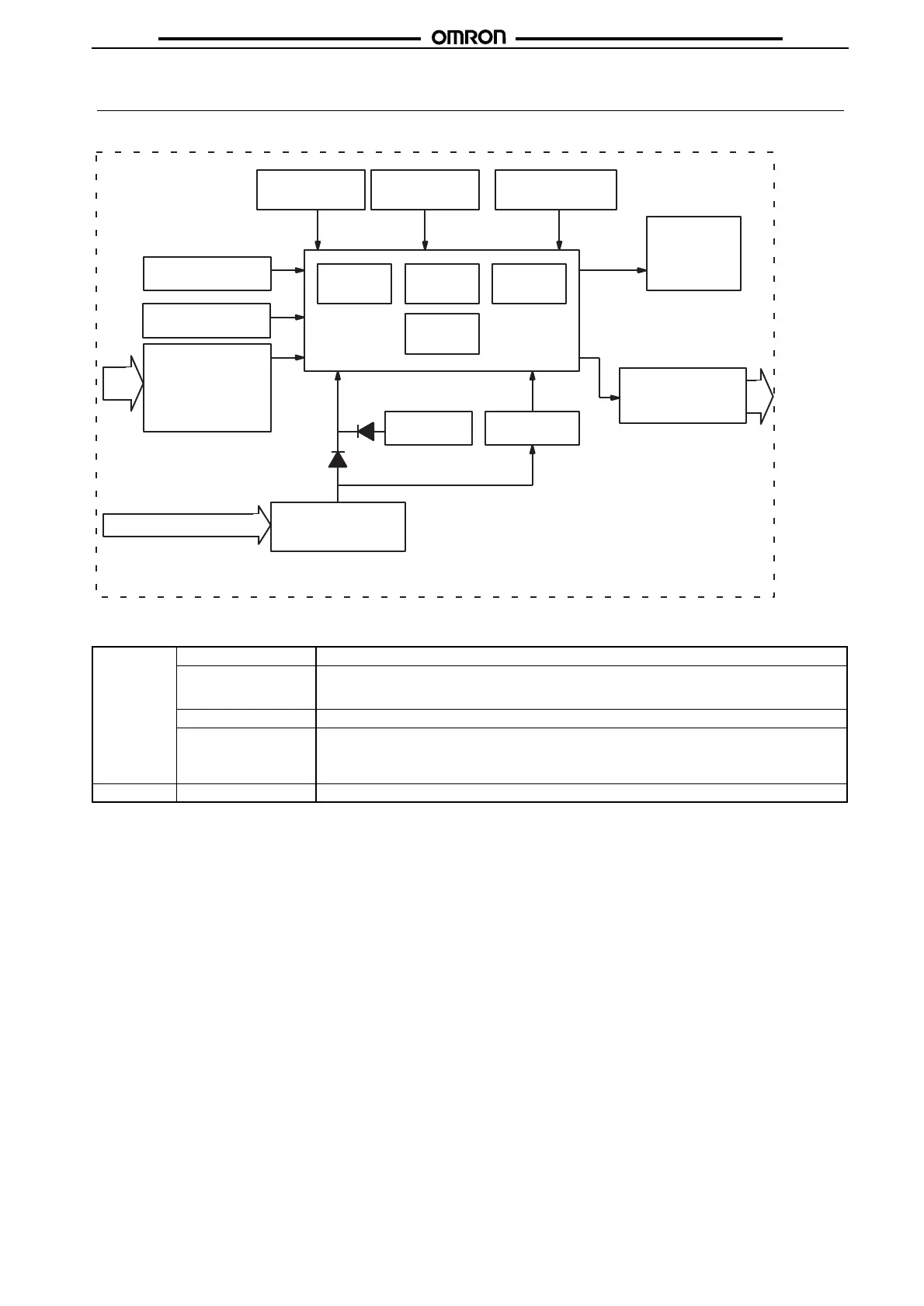
■ Block Diagram
■ I/O Functions
Inputs Start signal Stops timing in A-2 and A-3 (power on delay) modes. Starts timing in other modes.
Reset Resets present value (to zero in UP modes, to preset in DOWN mode).
Count inputs are not accepted while reset input is ON.
Reset indicator lit while reset input is ON.
Gate Inhibits timer operation.
Key protect Makes keys inoperative according to key protect level.
Key protected indicator lit while key protect input is ON.
Effective when power supply is turned off.
Effective when protect terminals are shorted.
Outputs Control output (OUT) Outputs made according to designated output mode when corresponding preset is reached.
Key switch circuits
Input circuits (Re-
set, control signal,
key protect, gate)
AC (DC) input
LCD drive
clock generator
RAM
Power circuits *
System clock
generator
ROM
Control
circuits
Battery
LCD reference
voltage generator
LCD driver
One-chip
microcom-
puter
Power outage
detector
Output circuits
(OUT)
Set
circuit
LCDs
* Power supply is not insulated from I/O.
DC input only for H5CR-S
 Loading...