H7CC-A@
6
Tachometer Function Ratings
* An input OFF time of at least 20 ms is required.
Characteristics
* Refer to the Life-test Curve.
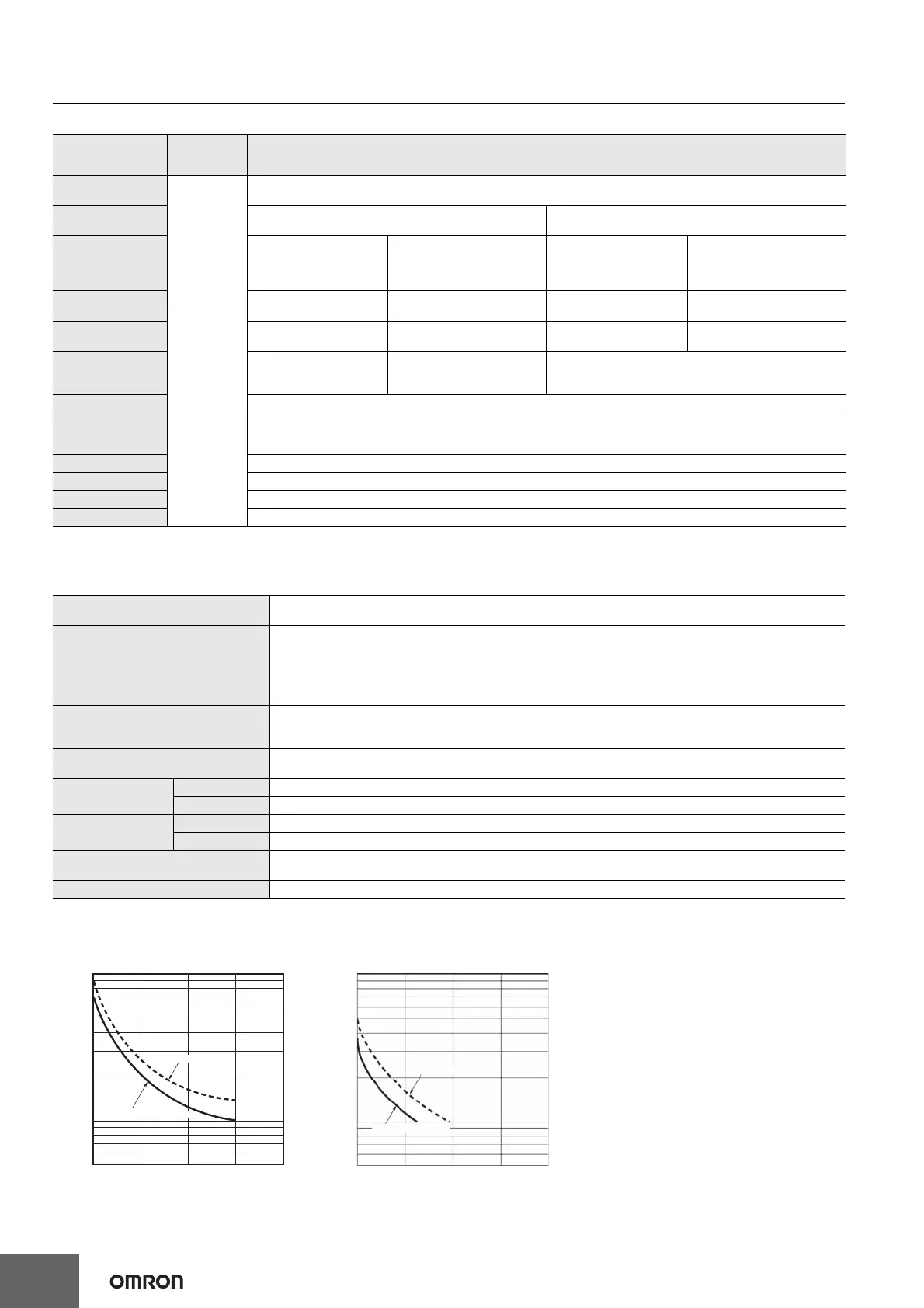
Life-test Curve (Reference Values)
Model
Item
H7CC-A8@
H7CC-A11@
H7CC-A@
H7CC-AW@/AU@
Input mode
No
tachometer
functionality
Selectable from 1 inputs, independent measurements for 2 inputs, differential input for 2 inputs, absolute ratio for 2 inputs,
and error ratio for 2 inputs.
Pulse measurement
method
Periodic measurement Pulse width measurement
Maximum counting
speed
30 Hz
(minimum pulse width: 16.7 ms)
1-input mode:
10 kHz
(minimum pulse width: 0.05 ms)
Other modes:
5 kHz
(minimum pulse width: 0.1 ms)
30 Hz
(minimum pulse width: 16.7 ms)
1-input mode:
10 kHz
(minimum pulse width: 0.05 ms)
Other modes:
5 kHz
(minimum pulse width: 0.1 ms)
Minimum input
signal width
--- --- 30 ms *
1-input mode: 0.2 ms
Other modes: 0.4 ms*
Measuring ranges 0.001 to 30.00 Hz
1-input mode: 0.001 to 10 kHz,
Other modes: 0.01 to 5 kHz
0.030 to 999999 s
1-input mode: 0.0002 to 999999 s
Other modes: 0.0004 to 999999 s
Sampling period 200 ms min.
200 ms min. or continuous
selectable (minimum interval of
10 ms)
Continuous (minimum interval of 10 ms)
Measuring accuracy ±0.1% FS ±1 digit max. (at 23 ±5°C)
Output mode
Input mode:
Not 2-input independent measurement: HI-LO, AREA, HI-HI, LO-LO
2-input independent measurement: HI-HI, LO-LO
Auto-zero time 0.1 to 999.9s
Startup time 0.0 to 99.9s
Averaging Simple averaging/moving averaging selectable, Processing: OFF, 2, 4, 8, or 16 times
Hold input Minimum input signal width: 20 ms
Insulation resistance
100 MΩ min. (at 500 VDC) between current-carrying terminals and exposed non-current-carrying metal parts,
and between non-continuous contacts
Dielectric strength
2,000 VAC, 50/60 Hz for 1 min between current-carrying metal parts and non-current-carrying metal parts
2,000 VAC, 50/60 Hz for 1 min between power supply and input circuit for all models except H7CC-@D@ (1,500 VAC
for 24 VAC/12 to 48 VDC)
1,500 VAC (for H7CC-@SD@), 50/60 Hz for 1 min between control output, power supply, and input circuit (2,000 VAC
for models other than H7CC-@SD@)
1,000 VAC, 50/60 Hz for 1 min between non-continuous contacts
Impulse withstand voltage
6.0 kV between power terminals (1.0 kV for models with 24 VAC/12 to 48 VDC)
6.0 kV between current-carrying terminals and exposed non-current-carrying metal parts (1.5 kV for models with 24
VAC/12 to 48 VDC)
Static immunity
Malfunction: 8 kV
Destruction: 15 kV
Vibration resistance
Destruction 10 to 55 Hz with 0.75-mm single amplitude each in three directions for 2 h each
Malfunction 10 to 55 Hz with 0.35-mm single amplitude each in three directions for 10 min each
Shock resistance
Destruction 300 m/s
2
each in three directions
Malfunction 100 m/s
2
each in three directions
Life expectancy
Mechanical: 10,000,000 operations min.
Electrical: 100,000 operations min. (3 A at 250 VAC, resistive load, ambient temperature condition: 23°C) *
Weight Approx. 120 g (Counter only)
Resistive load Inductive load
1,000
700
500
300
100
70
50
Load current (A)
01 2 34
30 VDC (cosφ=1)
250 VAC (cosφ=1)
No. of operations (
×
10
3
)
1,000
700
500
300
100
70
50
01 2 34
30 VDC (L/R=7 ms)
Load current (A)
250 VAC (cosφ=1)
No. of operations (
×
10
3
)
A current of 0.15 A max. can be switched at 125
VDC (cosφ=1) and current of 0.1 A max. can be
switched if L/R=7 ms. In both cases, a life of 100,000
operations can be expected.

 Loading...