Appendix 1 Specifications
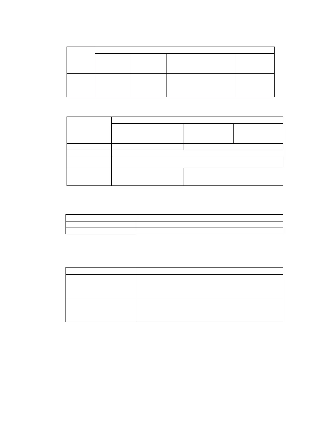
● Data Capacity Specifications
Specifications
Item
NS12-TS0@-V2
NS10-TV0@-V2
NS8-TV0@-V2
NS12-TS0@-V1
NS10-TV0@-V1
NS8-TV@@-V1
NS5-SQ0@-V1
NS5-SQ0@-V2
NS5-TQ0@-V2
NS5-MQ0@-V2
Standard
screen data
capacity
60 MB 20 MB NS8-TV0@-V1:
6 MB
NS8-TV1@-V1:
20 MB
6 MB 20 MB
● External Interface Specifications
Specifications
Item
NS12-TS0@-V1/-V2
NS10-TV0@-V1/-V2
NS8-TV@@-V1/-V2
NS5-SQ0@-V1
NS5-SQ0@-V2
NS5-TQ0@-V2
NS5-MQ0@-V2
USB HOST 1 port (for connecting printers) None
USB Slave 1 port (screen data transfer, connected to personal computer)
Memory card
interface
1 ATA-Compact Flash interface slot.
Used to transfer and store screen data and to store history data.
Expansion interface
(See note.)
For Expansion Interface Units
Used to install a Controller Link
Interface Unit or Video Input Unit.
For Expansion Interface Units
Used to install Expansion Units specially
designed for the NS5.
Note: This interface is for NS-series PTs only. Units not specified in this manual cannot be
installed.
● Programming Device (Software for Creating Screen Data)
Item Specifications
Name CX-Designer
Model NS-CXDC1-V@
A-1-3 Communications Specifications
• Serial Communications
Item Specifications
Port A Conforms to EIA RS-232C.
D-Sub female 9-pin connector
5-V output (250 mA max.) through pin 6
(See note 1.)
Port B Conforms to EIA RS-232C.
D-Sub female 9-pin connector (See note 2.)
5-V output (250 mA max.) through pin 6.
(See note 1.)
Note 1: The 5-V output of serial ports A and B cannot be used at the same time.
Note 2: With the NS5, the Expansion Interface on the Comm Tab Page in the System Menu set-
tings can be set to use a communications port in the expansion interface connector. The
expansion interface, however, is a future expansion, which cannot yet be used. Always
use the serial port B connector (D-Sub female 9-pin connector).
A-7
 Loading...


