3-7 Installing the Video Input Unit
3-7 Installing the Video Input Unit
A Video Input Unit (NS-CA001 or NS-CA002) can be mounted to an NS-series PT. Mounting
a Video Input Unit allows images from a video camera or vision sensor to be displayed on the
PT screen. This section explains how to connect a Video Input Unit to the PT with a cable us-
ing the NS-CA001 as an example.
It can be connected to an NS8, NS10, or NS12 PT. The Video Input Unit cannot be connected
to an NS5 PT.
Reference
Refer to the NS Series RGB and Video Input Unit Operation Manual (Cat. No. V086)
for information on NS-CA002 installation methods.
3-7-1 Video Input Unit Components
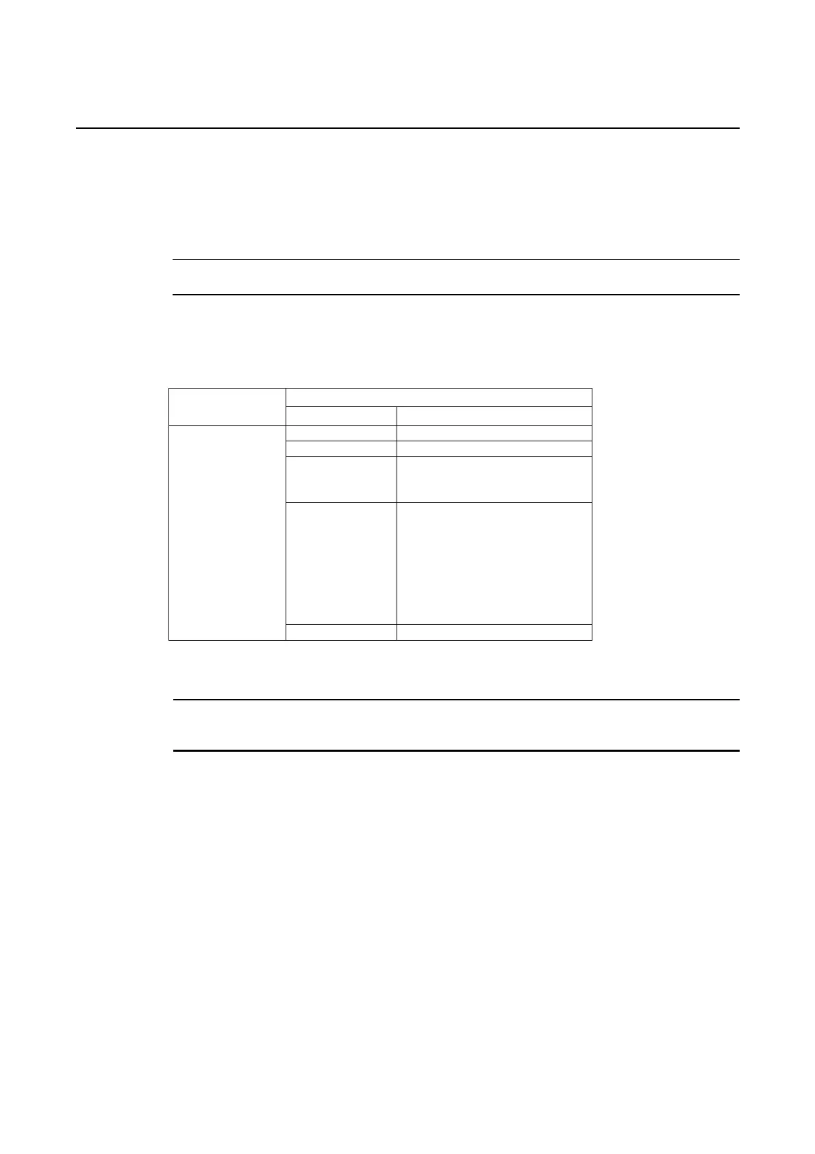
The following table shows the Video Input Unit's product configuration.
Model Components
Name Contents
Video Board (1) Allows video input. NS-CA001
Video Input Unit
Cover (1) Protects Video Board.
Cable (1) Connects the PT's functional
ground terminal and the cover to
prevent noise.
Screw (M3) (9) These screws are used for the
following:
•
•
•
Securing the Video Board to
the back of the PT.
Securing the cover to the
back of the PT.
Attaching the cable to the
cover.
Instruction sheet Instruction sheet for NS-CA001.
Note To comply with EC Directives (Low Voltage Directive) when mounting the Video Input Unit on
the PT, attach the PT to a control panel that has been cut to fit the size. (Refer to 3-1-3 Mount-
ing the PT to the Control Panel for panel cutout dimensions.)
3-27
 Loading...


