NX-CSG/SL5/SI/SO
15
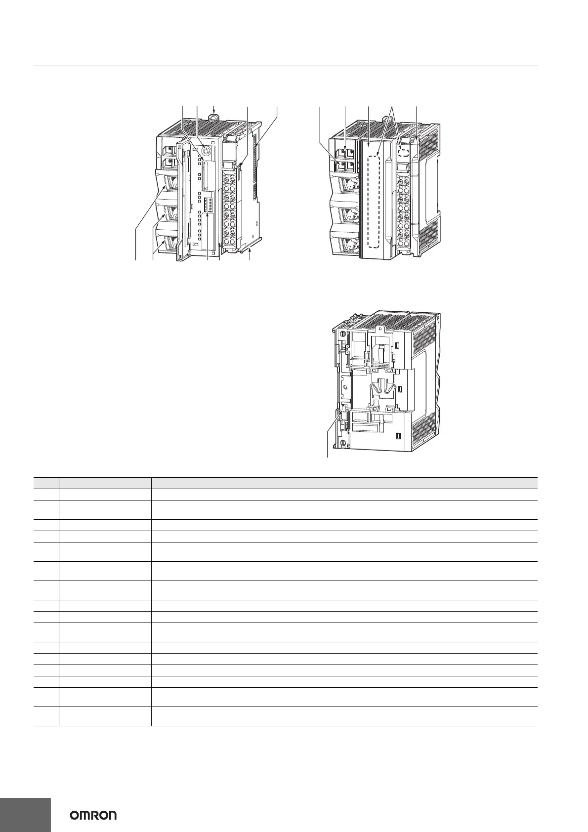
External Interface
Communication Control Unit NX-CSG320
Letter Name Function
(A) SD Memory Card connector Connects the SD Memory Card to the Communication Control Unit.
(B)
SD Memory Card power
supply switch
Turns OFF the power supply so that you can remove the SD Memory Card.
(C) DIN Track mounting hooks These hooks are used to mount the Unit to a DIN Track.
(D) Terminal Block Used for wiring the power supply and functional grounding wire.
(E) NX bus connector
This connector is used to connect the Communication Control Unit to the NX Unit on the right of the Communication Control
Unit.
(F)
IP Address Switch 2
(x16, x1)
Used for setting an IP address for the built-in EtherNet/IP port (PORT2A and PORT2B). Use the rotary switches and specify a
two-digit hexadecimal number.
(G)
IP Address Switch 1
(x16, x1)
Used for setting an IP address for the built-in EtherNet/IP port (PORT1). Use the rotary switches and specify a two-digit
hexadecimal number.
(H) SD Memory Card cover A cover for the SD Memory Card DIP switch area. It opens in the horizontal direction.
(I) Operation Status Indicators Show the operation status of Communication Control Unit by multiple indicators.
(J) End Cover
A cover to protect the Communication Control Unit and NX Unit. One End Cover is provided with the Communication Control
Unit as a standard accessory.
(K) DIN Track contact plate This plate is used to contact the functional ground terminal with a DIN Track.
(L) Unit hookup guides These guides are used to mount NX Units or End Cover.
(M) ID Information Indication Shows the ID information of the Unit.
(N) DIP Switch Used for backups. Normally, turn OFF all of the pins.
(O)
Built-in EtherNet/IP Port
(PORT2)
Connects the built-in EtherNet/IP with an Ethernet cable.
PORT2 consists of two RJ45 connectors (PORT2A and PORT2B) and has a built-in Ethernet switch.
(P)
Built-in EtherNet/IP Port
(PORT1)
Connects the built-in EtherNet/IP with an Ethernet cable.
(A) (B)
(E)
(C)
(D)
(G)
(M)
(H) (J)(I)
(N)(P) (O) (L)
(K)
(F)