S8VK-T
13
Wiring
• Connect the ground completely. A protective earthing terminal
stipulated in safety standards is used. Electric shock or malfunction
may occur if the ground is not connected completely.
• Minor fire may possibly occur. Ensure that input and output
terminals are wired correctly.
• Do not apply more than 75-N force to the terminal block when
tightening it.
• Be sure to remove the sheet covering the Product for machining
before power-ON so that it does not interfere with heat dissipation.
• To comply with safety standards and to ensure equipment safety,
connect the input to the S8VK-T through one of the following
Breakers or Fuses.
Power circuit-breakers
Note: Do not use the S8VK-T96024 with a DC input.
• Use the following material for the wires to be connected to the
S8VK-T to prevent smoking or ignition caused by abnormal loads
or phase failure.
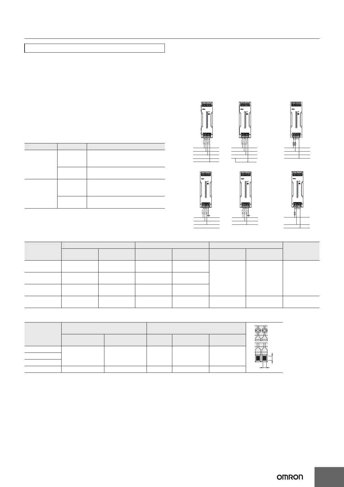
• Wire the input as shown in the following figures depends on your
power distribution system. Do not connect the neutral line in a
3-phase, 4-wire system.
Recommended Wire Type/Cross-sectional Area and Stripping Length
• The wire insertion hole, and applicable screwdriver of the terminal block are as follows.
Installation Environment
• Do not use the Power Supply in locations subject to shocks or
vibrations. In particular, install the Power Supply as far away as
possible from contactors or other devices that are a vibration
source. For usage onboard a ship, always attach an End Plate
(PFP-M) to both sides of the Power Supply to hold the Power
Supply in place.
• Install the Power Supply well away from any sources of strong,
high-frequency noise and surge.
Operating Life
• The life of a Power Supply is determined by the life of the
electrolytic capacitors used inside. Here, Arrhenius Law applies,
i.e., the life will be cut in half for each rise of 10°C or the life will be
doubled for each drop of 10°C. The life of the Power Supply can
thus be increased by reducing its internal temperature.
Ambient Operating and Storage Environments
• Store the Power Supply at a temperature of −40 to 85°C and a
humidity of 0% to 95%.
• Do not use the Power Supply in areas outside the derating curve
otherwise, internal parts may occasionally deteriorate or be
damaged.
• Use the Power Supply at a humidity of 0% to 95%.
• Do not use the Power Supply in locations subject to direct sunlight.
• Do not use the Power Supply in locations where liquids, foreign
matter, or corrosive gases may enter the interior of Products.
Precautions for Safe Use
Model Input Power circuit-breakers
S8VK-T12024
S8VK-T24024
3-phase
Circuit breaker Conforming UL/CE
480 V, 5 A, characteristic D, 3-pole, or
equivalent breaker
2-phase/DC
Fuse Conforming
UL/CE 600 V, 5 A
Fast Acting or identical function fuse
S8VK-T48024
S8VK-T96024
3-phase
Circuit breaker Conforming UL/CE
480 V, 5 A, characteristic D, 3-pole, or
equivalent breaker
2-phase/DC
Fuse Conforming
UL/CE 600 V, 10 A
Fast Acting or identical function fuse
L1
TN-S
L2
L3
N
PE
L1
TN-C
L2
L3
PEN
L1
FUSE
2-phase
L2
(L3)
PE
L1
TT
L2
L3
N
L1
IT
L2
L3
+
DC
-
PE
FUSE
Model
INPUT OUTPUT PE / Ground
Wire tripping
Length
American
Wire Gauge
Solid Wire
/Stranded Wire
American
Wire Gauge
Solid Wire
/Stranded Wire
American
Wire Gauge
Solid Wire
/Stranded Wire
S8VK-T12024 AWG22 to 10
0.35 to 6 mm
2
/0.35 to 4 mm
2
AWG18 to 10
0.75 to 6 mm
2
/0.75 to 4 mm
2
AWG14 to 10
2.5 to 6
mm
2
/2.5 to 4
mm
2
8 to 10 mmS8VK-T24024 AWG22 to 10
0.35 to 6 mm
2
/0.35 to 4 mm
2
AWG14 to 10
2.5 to 6 mm
2
/2.5 to 4 mm
2
S8VK-T48024 AWG20 to 10
0.5 to 6 mm
2
/0.5 to 4 mm
2
AWG12 to 10
4 to 6 mm
2
/4 mm
2
S8VK-T96024 AWG16 to 6
1.5 to 16 mm
2
/1.5 to 16 mm
2
AWG8 to 6
10 to 16 mm
2
/10 to 16 mm
2
AWG14 to 6
2.5 to 16
mm
2
/2.5 to 16
mm
2
13 to 16 mm
Model
Wire Insertion Hole
(Refer to the diagram on the right)
Applicable Screwdriver
W L No.
Driver
Diameter
Length
S8VK-T12024
2.9 2.9 #2 4.9 mm max. 10 mm min.S8VK-T24024
S8VK-T48024
S8VK-T96024 5.4 5 #2 5.1 mm max. 12 mm min.
W
L
 Loading...