S8VK-T
14
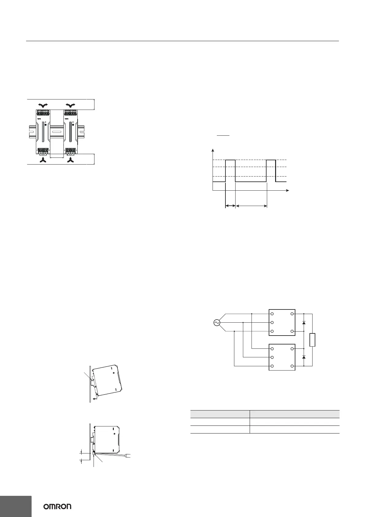
Mounting
• Take adequate measures to ensure proper heat dissipation to
increase the long-term reliability of the Product. Be sure to allow
convection in the atmosphere around devices when mounting. Do
not use in locations where the ambient temperature exceeds the
range of the derating curve.
• When cutting out holes for mounting, make sure that cuttings do
not enter the interior of the Products.
• Improper mounting will interfere with heat dissipation and may
occasionally result in deterioration or damage of internal parts. Use
the Product within the derating curve for the mounting direction that
is used.
Overload Protection
• Internal parts may possibly deteriorate or be damaged if a
short-circuited or overcurrent state continues during operation.
• Internal parts may possibly deteriorate or be damaged if the Power
Supply is used for applications with frequent inrush current or
overloading at the load end. Do not use the Power Supply for such
applications.
• The DC ON indicator (green) flashes if the overload protection
function operates.
Charging a Battery
If you connect a battery as the load, install overcurrent control and
overvoltage protection circuits.
Output Voltage Adjuster (V.ADJ)
• The output voltage adjuster (V.ADJ) may possibly be damaged if it
is turned with unnecessary force. Do not turn the adjuster with
excessive force.
• After completing output voltage adjustment, be sure that the output
capacity or output current does not exceed the rated output
capacity or rated output current.
DIN Rail Mounting
To mount the Block on a DIN Rail, hook portion (A) of the Block onto
the rail and press the Block in direction (B).
To dismount the Block, pull down portion (C) with a flat-blade
screwdriver and pull out the Block.
Power Boost Function
For All Models
Power Boost is a function that can output the temporary repeated
boost current larger than the rated current.
However, it should meet the following four Boost current conditions.
1. Time that the boost current flows: t1
2. The maximum value of the boost current: lp
3. The average output current: lave
4. The time ratio of the boost current flow: Duty
Note: Boost current conditions
• Do not allow the boost current to continue for more than 10
seconds.
Also, do not let the duty cycle exceed the boost current conditions.
These conditions may damage the Power supply.
• Ensure that the average current of one cycle of the boost current
does not exceed the rated output current.
This may damage the Power Supply.
• Lessen the load of the boost load current by adjusting the ambient
temperature and the mounting direction.
• Power Boost Function is not possible for the S8VK-T 960 W at
2-phase input or in parallel operation.
Series Operation
Two power supplies can be connected in series.
Note: 1. The diode is connected as shown in the figure. If the load is
short-circuited, a reverse voltage will be generated inside
the Power Supply. If this occurs the Power Supply may
possibly deteriorate or be damaged. Always connect a
diode as shown in the figure.
Select a diode having the following ratings.
2. Although Products having different specifications can be
connected in series, the current flowing through the load
must not exceed the smaller rated output current.
*1. Convection of air
*2. 20 mm min.
*1
*1
*2
(B)
(A)
(C)
30 mm min.
Rail stopper
Type Schottky Barrier diode
Dielectric strength (V
RRM) Twice the rated output voltage or above
Forward current (I
F) Twice the rated output current or above
• t1
• Ip
• lave
≤ 10 s
≤ Rated boost current
≤ Rated current
Duty=
t1 + t2
t1
× 100 [%] ≤ 30%
[A]
Ip: Boost current
Rated current
lave: Average current
t2
t1
output current
+V
−V
+V
−V
L1
L2
L3
L2
L1
L3
Load
 Loading...