Switch Mode Power Supply S8VM 7
Engineering Data
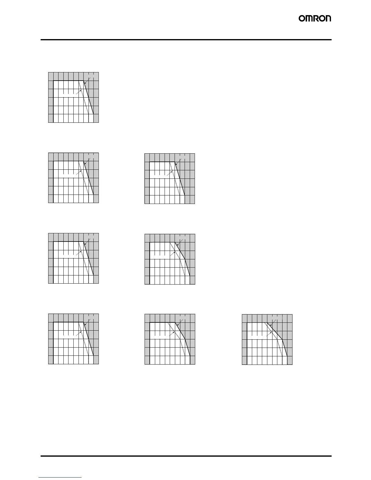
� Derating Curve
Note: 1. Internal parts may occasionally be deteriorated or damaged. Do not use the Power Supply in areas outside the derating curves (i.e., the
area shown by shading
A in the above graphs).
2. If there is a derating problem, use forced air-cooling.
3. When mounting two or more Power Supplies side-by-side, allow at least 20 mm spacing between them. Multiple 100- and 150-W model
s
cannot be used side by side. Be sure to install the Power Supplies as far away from heat-generating sources as possible. As a reference
value, allow at least 50 mm spacing on the right and left sides. If only 20 mm spacing is allowed, use the Power Supply at a load ratio of
80% or less.
4. When using 150-W models for a long period of time at an input voltage of 90 VAC or lower, reduce the load to 80% or less of the above
derating curves.
S8VM-15W/30W
Standard mounting/Horizontal mounting/Face-up mounting
S8VM-50W
Standard mounting/Horizontal mounting
Face-up mounting
S8VM-100W
Standard mounting
Horizontal mounting/Face-up mounting
S8VM-150W
Standard mounting Horizontal mounting
Face-up mounting
−20 −10 0 10 20 30 40 50 60 70 80
120
100
80
60
40
20
0
Ambient temperature (
°C
 Loading...