Switch Mode Power Supply S8VM 19
Safety Precautions
� Precautions for Safe Use
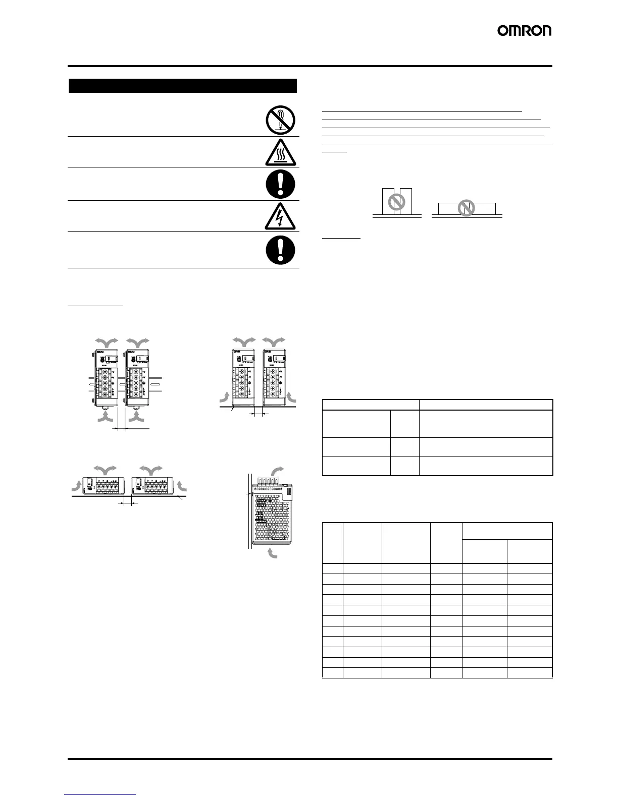
Mounting
Take adequate measures to ensure proper heat dissipation to
increase the long-term reliability of the Product.
Be sure to allow convection in the atmosphere around devices when
mounting. Do not exceed the range of the derating curve.
Use the metal plate as the mounting panel.
When cutting out holes for mounting, make sure that cuttings do not
enter the interior of the Product.
Improper mounting will interfere with heat dissipation and may
occasionally result in deterioration or damage of internal parts.
Use the Product within the derating curve for the mounting direction
that is used.
When mounting two or more Power Supplies side-by-side, allow at
least 20 mm spacing between them, as shown in the above
illustrations.
The internal parts may possibly be damaged if mounting screws are
over inserted. Refer to Dimensions on page 12 for maximum depth of
insertion inside the Power Supply.
Several Power Supplies cannot be connected. (Only S8VM-
100@@@@/150@@@@) Keep the Power Supply as far away from
heating elements as possible when installing. As a reference value,
allow at least 50 mm spacing on the right and left sides. If only 20
mm spacing is allowed, use the Power Supply at a load ratio of 80%
or less.
Wiring
Connect the ground completely. A protective earthing connection
stipulated in safety standards is used. Electric shock or malfunction
may occur if the ground is not connected completely.
Minor fire may possibly occur. Ensure that input and output terminals
are wired correctly.
Do not apply more than 100 N force to the terminal block when
tightening it.
Be sure to remove the sheet covering the Product for machining
before power-ON so that it does not interfere with heat dissipation.
Use the following material for the wires to be connected to the S8VM
to prevent smoking or ignition caused by abnormal loads.
Over heating or fire can result from inadequately sized wiring
materials when problems occur at the load. As a general rule, always
select wire sizes suitable for at least 1.6 times the rated current.
Recommended Wire Types
Selection of Wires
Select wires for the Power Supply carefully. Refer to this table when
selecting the wires.
Minor electric shock, fire, or Product failure may
occasionally occur. Do not disassemble, modify, or repair
the Product or touch the interior of the Product.
Minor burns may occasionally occur. Do not touch the
Product while power is being supplied or immediately
after power is turned OFF.
Fire may occasionally occur. Tighten terminal screws to
the specified torque of 1.6 N·m.
Minor injury due to electric shock may occasionally occur.
Do not touch the terminals while power is being supplied.
Minor electric shock, fire, or Product failure may
occasionally occur. Do not allow any pieces of metal or
conductors or any clippings or cuttings resulting from
installation work to enter the Product.
Standard mounting
(DIN Rail mounting bracket type)
Standard mounting
(Front-mounting type)
Horizontal mounting
(Front-mounting type)
Face-up mounting
(Front-mounting type)
!CAUTION
(See note 3.)
(See
note 1.)
(See
note 1.)
(See note 1.)
(See note 2.)
(See
note 1.)
(See note 3.)
Note: 1. Convection of air
2. 20 mm or more
3. Use a metal plate as the
mounting panel.
(See note 1.)
(See note 3.)
Model Recommended wire type
S8VM-015@@@@
S8VM-030@@@@
S8VM-050@@@@
(M3.5)
AWG24 to 14 (0.205 to 2.081 mm
2
)
S8VM-100@@@@
S8VM-150@@@@
(M3.5)
AWG24 to 14 (0.205 to 2.081 mm
2
)
S8VM-100@@@@
S8VM-150@@@@
(M4)
AWG24 to 12 (0.205 to 3.309 mm
2
)
AWG
No.
Cross-
sectional
area (mm
2
)
Configuration
(number of
conductors/
mm)
Voltage
drop per
1 A (mV/
meter)
Recommended maximum
current (A)
UL1007
(300 V at
80
° C)
UL1015
(600 V at
105° C)
30 0.051 7/0.102 358 0.12 ---
28 0.081 7/0.127 222 0.15 0.2
26 0.129 7/0.16 140 0.35 0.5
24 0.205 11/0.16 88.9 0.7 1.0
22 0.326 17/0.16 57.5 1.4 2.0
20 0.517 26/0.16 37.6 2.8 4.0
18 0.823 43/0.16 22.8 4.2 6.0
16 1.309 54/0.18 14.9 5.6 8.0
14 2.081 41/0.26 9.5 --- 12.0
12 3.309 65/0.26 6.0 --- 22.0
10 5.262 104/0.26 3.8 --- 35.0
S8VM-100@@@@/S8VM-150@@@@
Incorrect Incorrect
 Loading...