3
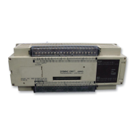
Beneath the cover are the DIP switch and the socket where an EP–ROM
chip may be installed. For details, see 2–7–1 Setting the CPU Dipswitch and
2–7–2 EP–ROM Installation. Only DIP switch pins 1 and 2 are on when the
CPU is delivered.
ROM socket
8 Turn ON to use hardware reset (0001).
7 Turn OFF if HDM(61) is not used.
6 Turn ON for English display.
5 Turn ON to inhibit ALARM indicator.
4, 3 ROM: ON (RAM: OFF)
2, 1 RAM: ON (ROM: OFF)
CAUTION: In case of battery failure, data stored in
the RAM, the DM area, the HR area, etc., will not be preserved.
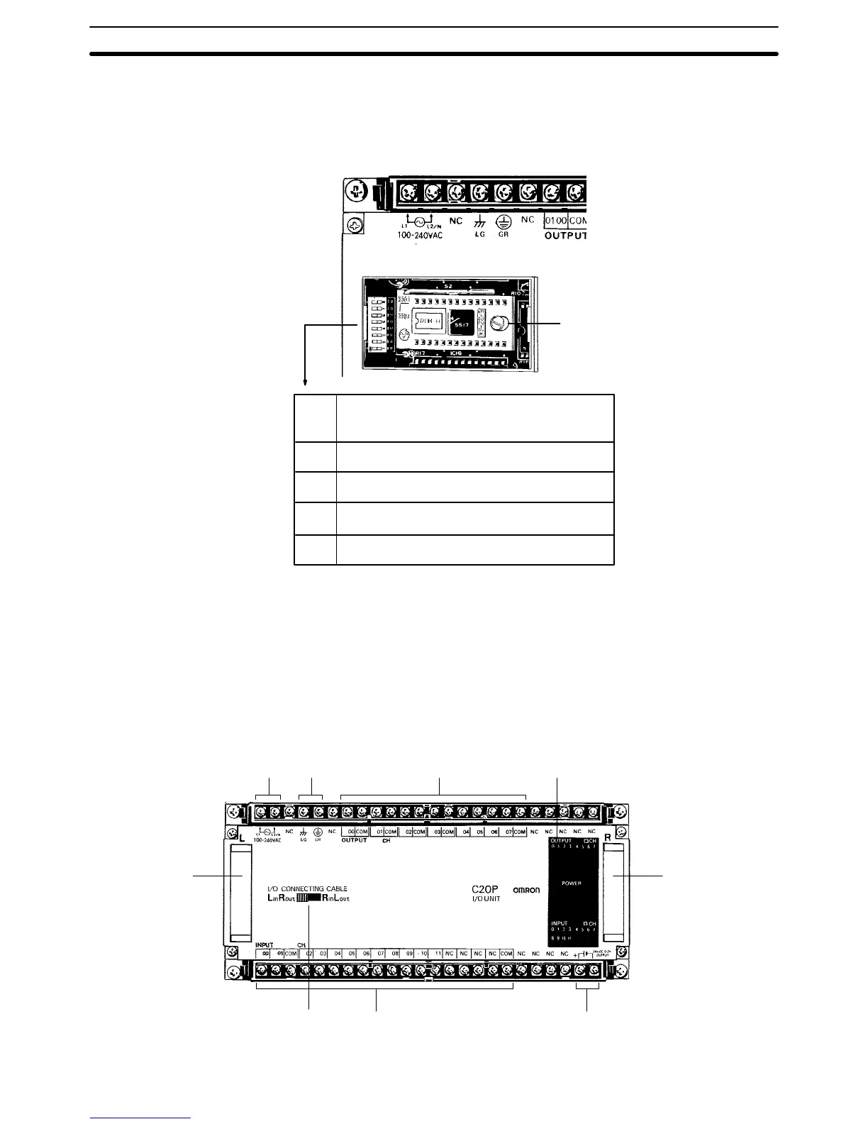
1–1–2 Expansion I/O Units
In the diagram below, the C20P is shown as a representative model. Refer to
Appendix A Standard Models for your model’s exact specifications.
Power supply Ground Outputs Indicators
CPU,
Expansion
I/O Unit,
Analog
Timer Unit, or
I/O Link Unit
connector
24–VDC outputInputsCPU left/right
selector
CPU,
Expansion
I/O Unit, or
I/O Link Unit
connector
ROM Socket and DIP
Switch
Nomenclature Section 1–1
 Loading...