52
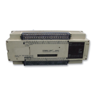
2. Using a Phillips screwdriver to loosen the 4 screws, remove the cover from
the Unit, lifting it from the left.
3. Pull the battery from the holder and install the new one within five minutes.
Battery in holder
4. Replace the cover, positioning it over the Unit and snapping it into place by
applying pressure to the area marked ”OMRON.”
5. Clear the ALARM on the Programming Console.
3–4 Preventive Measures
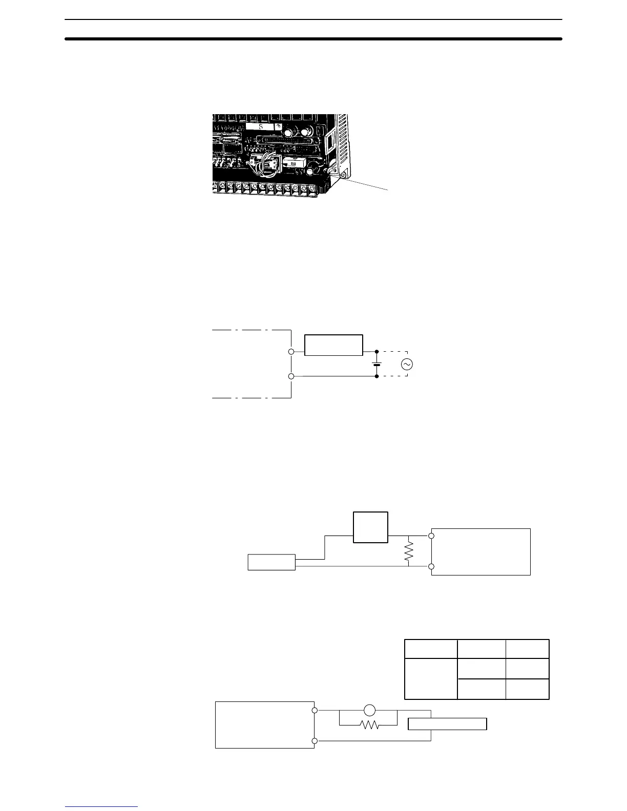
Load Circuit Fuses A fuse in the load circuit will protect the output elements, circuit board, etc., in
the event of a short in the output device.
Relay,
solenoid, etc.
+
OUT
COM
When two–wire sensors, such as photoelectric sensors and proximity sen-
sors, or limit switches with neon lamp are connected to the CPU as input de-
vices, the input signal may be erroneously turned ON by a leakage current
over 1.5 A. To prevent this, connect a bleeder resistor as shown below.
Determine the resistance of the bleeder resistor by the following equation,
where I is the leakage current.
Sensor
Input
Power
supply
Bleeder resistor
7.5 k
Ω max.
PC
R
R = 17.15/3.431 + 5 (k
Ω max.)
Likewise, if there is a danger of leakage current causing a transistor or triac
to malfunction, connect a bleeder resistor as shown below. Determine the
resistance of the bleeder resistor by the following equation.
Transistor
Triac
24 VDC
100 VAC
200 VAC
0.1 mA
2.0 mA
5.0 mA
R < Von/I
Von = ON voltage of the load (V)
I = leakage current (mA)
R = bleeder resistance (k
Ω)
L
Load power supply
OUT
COM
Bleeder resistor
Prevention of Input
Leakage Current
Prevention of Output
Leakage Current
Preventive Measures Section 3–4
 Loading...