18
Connecting I/O Link Units One I/O Link Unit can be connected directly to a CPU or to any combination
of a CPU and Expansion I/O Units. It cannot be used in the same PC System
with an Analog Timer Unit.
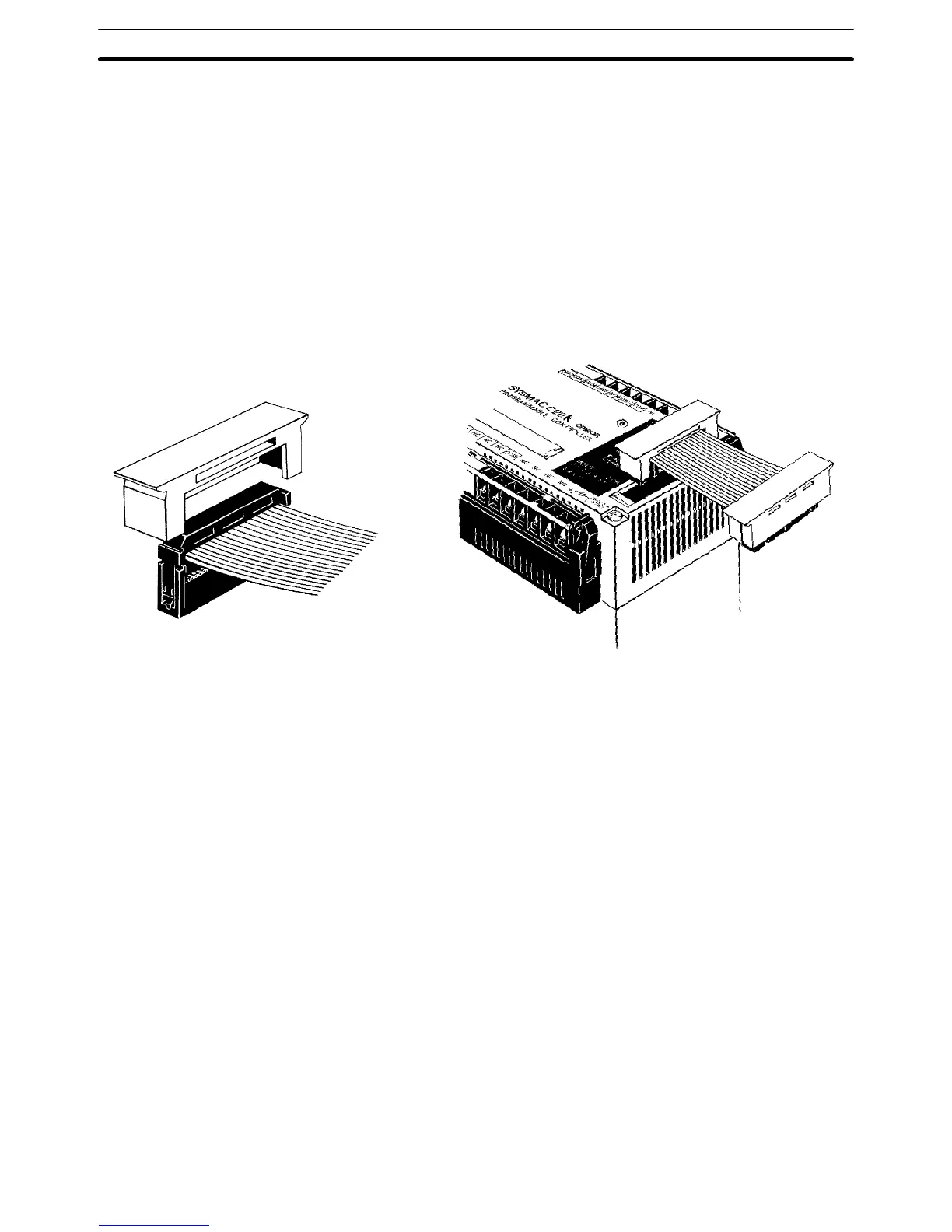
Connection Procedure Follow these four steps to connect Expansion I/O Unit, Analog Timer, and I/O
Link Unit Connecting Cables.
1, 2, 3... 1. Remove the connector cover from the CPU, using a screwdriver if nec-
essary.
2. Insert one of the cable’s connectors into the cover. (Once inserted, the
connector cannot be removed.)
3. Reinsert the cover/connector combination into the CPU.
4. Repeat this procedure on the other end of the cable.
Cover
Optical Fiber Cable Optical fiber cable can be used for extending transmission distance and re-
ducing noise. There are three types, and the appropriate cable for any given
situation will depend on the desired transmission distance and the particular
Units which need to be connected.
All–plastic optical fiber cable (APF) is for short–distance transmission (up to
20 m) and can be used only by Units with the suffix ”–P” attached. Plastic–
clad optical fiber cable (PCF) is for middle–distance transmission (up to 200
m for Units with ”–P” and 800 m for Units without ”–P”). Crystal optical fiber
cable (AGF) is for long–distance transmission (up to 3 km) and can be con-
nected only to certain Link Adapters.
Although laying optical fiber cable does not basically differ from laying wire
cable, there are certain precautions which should be observed. For details,
refer to the Optical Remote I/O Systems manual.
Link Adapters Although it is normally possible to connect Units in series, a failure (power
failure, disconnection, etc.) in one of the Units will cause all the subsequent
Units to cease operating. You can use Link Adapters to prevent this type of
situation from occuring. Even if a power failure occurs in a Unit connected to
a branch line of a Link Adapter, the Link Adapter will bypass that Unit and
continue to transmit signals to the other Units. You can also use Link Adapt-
ers for branching and for converting between various types of wire and opti-
cal cable. For details on these and other functions of Link Adapters, refer to
the Link Adapter manual.
I/O Connecting Cable Section 2–4
 Loading...