COMPARTMENT
SIZE
AND LOCATION
COMPARTMENT
SIZE
AND LOCATION
Compartment location is determined largely by:
1.
Physical size.
2.
Access opening.
3. Mounting support—most important of all.
Physical
Size
The area in the vehicle for the electric generating set
must be large enough for the compartment, with
specified minimum clearance between the electric
generating set and compartment walls or ceiling (and
acoustical material, if used.) See Figure 2.
ACCESS
OPENING
Plan the location for an access opening large enough
to permit set removal. Compartment door should be
designed for easy removal or for easy access for
operator or service personal.
MOUNTING
SUPPORT
Because of compartment weight, the most desirable
mounting location is between the main frame
members of the recreational vehicle. However, this is
seldom possible. Most common installations are on
the side of the vehicle and most difficult to.reinforce.
One side of the compartment is fastened to the frame
and the opposite side secured to the body. Compart-
ment floor must be metal.
Channel,
box or angle iron can be used for a com-
partment frame with a sheet metal cover.
COMPARTMENT
WARNING
J
1.
Compartment or installation area must be separ-
ated from living quarters by a vapor-tight
wall.
WARNING I Separate installation area or compart-
•MMBM^HJI
ment from living quarters by a vapor-
tight wall to prevent entrance of noxious fumes to interior and
possible asphyxiation hazard.
2.
Line the compartment or separate from living
quarters with a fire barrier of sheet metal or other
noncombustible material. The compartment can
also be readily sealed and lends itself easily to
sound or accoustical treatment.
Do not use flammable material directly
above or around the electric generating
set compartment. Heat transferred through the sheet metal
compartment structure or other material can be HOT enough
to discolor, char or ignite fiberboard, seat cushions, etc. Use
of asbestos or other noncombustible temperature insulating
material in high temperature areas may be necessary.
See Figure 2 for minimum clearances and com-
partment size.
DO NOT use absorbent sound proofing material
oncompartmentfloor. Thefloorshould have
min-
imum openings to reduce entrance of road dirt.
Compartment floor must be so constructed as to
prevent accumulation of oil, fuel or water in any
corner. Drainage can be accomplished through
the use of a 1/2" diameter hole near each corner
or other suitable means.
WARNING
1
Be sure holes are not directly above
muffler to prevent fire hazard.
VIBRATION
ISOLATORS
Rubber vibration isolators are furnished with all Onan
recreational vehicle models.
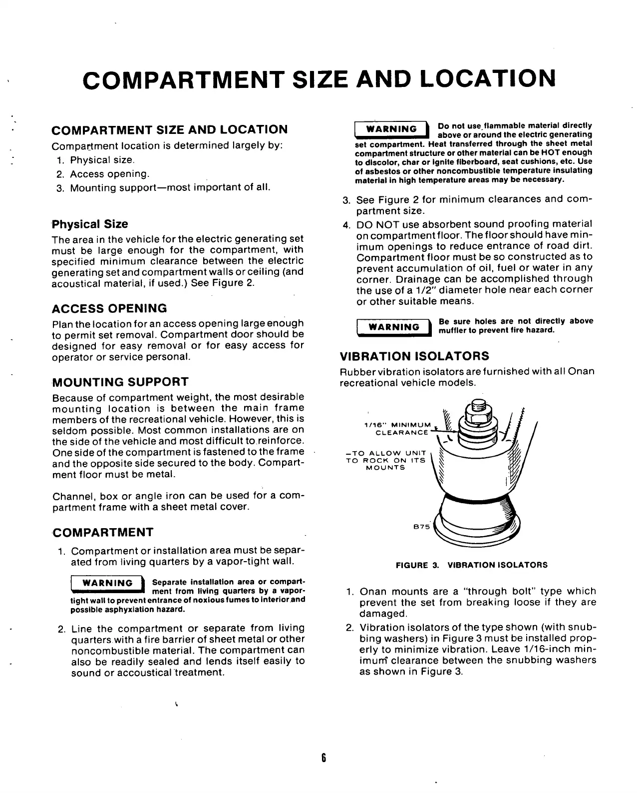
1/16" MINIMUM
CLEARANCE
—
TO ALLOW UNIT
TO
ROCK ON ITS
MOUNTS
B75
FIGURE 3. VIBRATION ISOLATORS
1.
Onan mounts are a "through bolt" type which
prevent the set from breaking loose if they are
damaged.
2.
Vibration isolators of the type shown (with snub-
bing washers) in Figure 3 must be installed prop-
erly to minimize vibration. Leave
1/16-inch
min-
imum'
clearance between the snubbing washers
as shown in Figure 3.
 Loading...
