16
REMOTE CONTROL CONNECTIONS
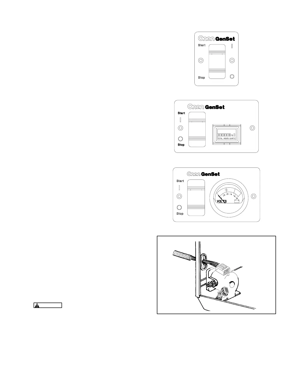
Onan offers three varieties of remote control panel:
• Remote start/stop switch with status indicator
light only (Figure 15).
• Remote start/stop switch with status indicator
light and hour meter (Figure16).
• Remote start/stop switch with status indicator
light and DC voltmeter (Figure17).
The genset has an 8-pin connector for remote con-
trol connections (Figure 18). Remote control wiring
harnesses in several lengths are available sepa-
rately. To make connections to a remote control
panel:
1. Push the remote control wire harness connec-
tor through the entrance hole in the side of the
genset housing and snap it together with the
genset connector. If the wiring harness is made
up by others, insulated 18 AWG copper con-
ductors should be used for distances up to 30
feet (9 metres) and heavier gauge conductors
for distances that are greater. Use flexible
sheathing to protect remote control wiring. Fig-
ure 19 is a schematic of typical remote control
connections. It identifies the function of each
connector pin number. The remote panel end of
each lead should be marked to identify the con-
nector pin number.
2. Route control leads separately from AC power
leads to reduce the possibility of erratic opera-
tion due to false induced signals.
3. Seal the opening where the leads enter the ve-
hicle interior with silicone rubber or an equiva-
lent type of sealant to keep out exhaust gas.
WARNING
EXHAUST GAS IS DEADLY!
Seal all wiring openings into the vehicle in-
terior to keep out exhaust gas.
FIGURE 15. REMOTE CONTROL
FIGURE 16. REMOTE CONTROL / HOUR METER
FIGURE 17. REMOTE CONTROL / DC VOLTMETER
FIGURE 18. REMOTE CONTROL CONNECTOR
Redistribution or publication of this document,
by any means, is strictly prohibited.
 Loading...


