DX-C390
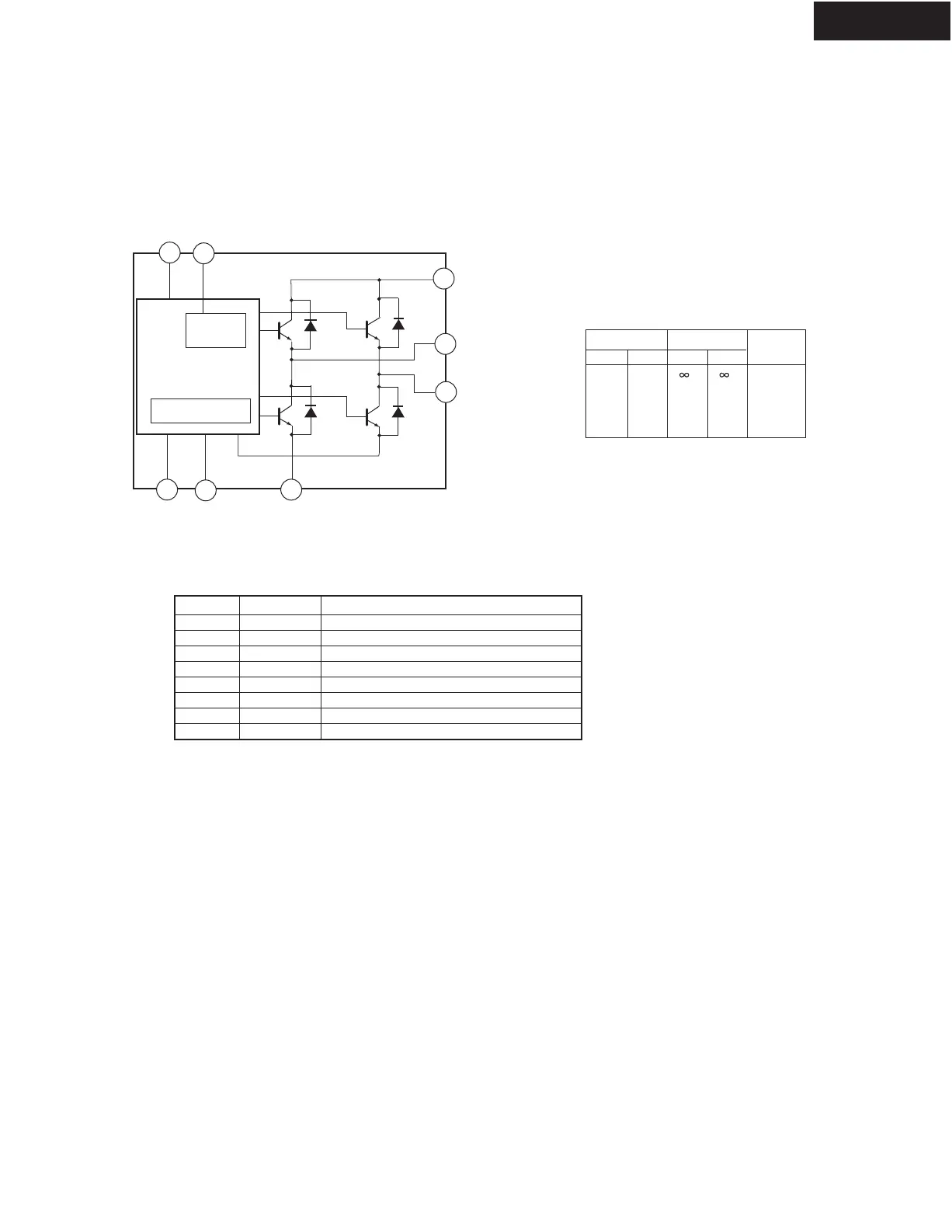
IC BLOCK DIAGRAM/ TERMINAL DESCRIPTION
2
8
6
7
3
5
1
9
Reg.. Power
Supply
Vcc Vref
Vss
OUT1
OUT2
GNDIN1
IN2
Q601, Q602 : TA7291S (MOTOR DRIVER)
Protection
circuit
INPUT OUTPUT
IN1 IN2 OUT1 OUT2
0
1
0
1
0
0
1
1
H
L
L
H
L
L
MODE
STOP
CW/CCW
CCW/CW
BRAKE
CW: Clockwise direction
CCW: Counter clockwise direction
Truth table
PIN No.
2
6
8
5
9
1
7
3
SYMBOL
Vcc
VS
Vref
GND
IN1
IN2
OUT1
OUT2
FUNCTUIN DESCRIPTION
Supply voltage termunal for Logic.
Supply voltage terminal for Motor drive.
Supply voltage terminal for control.
GND
Input
Input
Output
Output
Pin 4 : NC
PIN FUNCTION
BLOCK DIAGRAM
 Loading...