Do you have a question about the Onkyo TX-8020B and is the answer not in the manual?
| Receiver type | stereo |
|---|---|
| Audio output channels | - channels |
| Signal-to-Noise Ratio (SNR) | 100 dB |
| Total Harmonic Distortion (THD) | 1 % |
| Power output per channel (20-20KHz@8 Ohm) | 90 W |
| Connectivity technology | Wired |
| Speakers connectivity type | - |
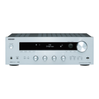
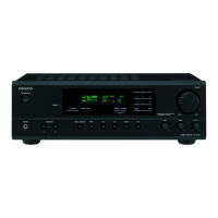
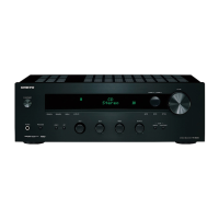
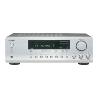
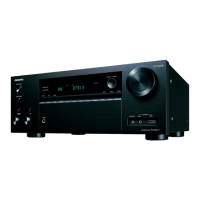
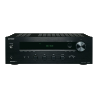
| Product color | Black |
| Apple docking compatibility | Not supported |
| AC input frequency | 50 Hz |
| Power consumption (typical) | 170 W |
| Package weight | 9600 g |
| HDMI in | 0 |
| Audio (L/R) in | 5 |
| Digital audio coaxial in | 2 |
| Digital audio optical in | 1 |
| Multichannel audio input type | Terminals |
| Ethernet LAN | No |
| RDS features | PS, PTY, RT, TP |
| Supported radio bands | AM, FM |
| Preset stations quantity | 40 |
| Depth | 150 mm |
|---|---|
| Width | 435 mm |
| Height | 328.5 mm |
| Weight | 7300 g |
Details power output per channel and amplifier technologies used.
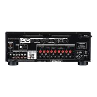
Lists available analog, digital, and phono inputs, plus speaker terminals.
Covers bass, treble, balance controls, remote operation, and sleep timer.
Essential safety measures for servicing the unit, including grounding and tool selection.
Instructions for replacing fast and slow-acting fuses, emphasizing correct type.
Procedures for initial unit setup and firmware version verification.
Confirms firmware version, voltage, and current protection operations.
Verifies remote control, headphone, and RDS functionality.
Monitors thermal sensor, output sensors, and general terminal operations.
Steps to initialize unit memories for shipping and check knob positions.
Detailed guide to entering and navigating various test modes for component checks.
Lists frequencies for FM and AM bands automatically stored in test mode presets.
Method for checking temperature and VOLH values using Enter + Standby.
Illustrates key parts and their locations, including boards, chassis, and heatsink.
Diagram of the rear panel showing various input/output connectors and terminals.
Details the heatsink assembly and associated power transistors.
Lists transistors and chassis components for MDC (120V) and MPP (230V) models.
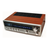
Details front panel, rear panel, and cabinet parts for specific models.
Lists fuses, connectors, and PC board assemblies for different model variants.
Lists transistors, screws, and chassis components for the silver unit.
Details front panel, clear plate, and various control knobs for the silver model.
Lists fuses, connectors, and PC board part numbers for the silver model.
Detailed schematic of the Amplifier PC Board (BAAF-1472), including input/output signals.
Illustrates how audio signals flow through the amplifier section and connect to other boards.
Shows the layout and connections of components on the Amplifier section board.
Detailed circuit diagram for amplifier channels L/0, R/4, L/1, R/5, L/2, R/6.
Shows how power supply voltages are distributed to the amplifier stages.
Illustrates the output transistors and related components for each speaker channel.
Detailed circuit diagram for the Class-A amplifier stage (U0020).
Instructions for adjusting bias current (quiescent current) in the amplifier.
Lists specific components within the Class-A amplifier section and their values.
Diagram of the thermal sensing component (Q6300A) and its connection.
Shows the connection of the thermal sensor board (U0012) to the main board (BADG-1474).
Diagram of the terminal board (U0011) and its pin assignments.
Details the pin configurations for sockets and plugs on the terminal board.
Illustrates connections made via wire harnesses and jumper leads.
Diagram of the headphone jack (U0014) and its associated components (L5501-L5503).
Shows how headphone signals (HP_L, HP_R) and ground are routed.
Circuitry for driving the FL display, including signal input and control pins.
Shows connections for front panel buttons (KEY0, KEY1, etc.) and volume control.
Details connections between the display board and other boards (BAETC-1442).
Circuit diagram for Bass and Treble controls (U0033).
Schematic for the balance control circuit.
Circuit for the input selector switch (U0032) on the Input/Bass PC Board.
Diagram of the standby switch (S708) and associated components.
Shows the circuit for the standby LED (LEDSTBY).
Diagram showing connections for Speaker A and B terminals.
Illustrates output relays (RL6801, RL6802) and protection components.
Shows the path of the SW_OUT signal and its connections.
Diagram of the MPU board (U0035) showing its pins and external connections.
Illustrates the signal routing for various functions controlled by the MPU.
Detailed diagram of the power supply board (U0036), including transformers and regulators.
Lists the various voltage outputs (+12V, +10V, etc.) from the power supply.
Shows fuse ratings and AC power cord input details.
Diagram of the tuner PC board (BARF-1450) and its internal components.
Illustrates the signal flow for radio frequency (RF) and intermediate frequency (IF) stages.
Shows control signals like VDD, GND, and data lines for the tuner.
Diagram of the digital PC board (BADG-1269) showing its complex circuitry.
Details connections between the microprocessor and other digital components.
Details pads, sheets, tape, and cartons used in packaging.
Lists accessories like poly bags, warranty cards, and instruction manuals.
Differentiates packing parts for MDC (Black) and MPP (Silver) models.