5923704 DEC 2022
X-ZONE T
Read this operation manual carefully before use to ensure proper operation of this product.
Failure to read this operation manual may cause improper operation and may result in serious injury or death of a person.
The meanings of the symbols are as follows.
1. This product is a non-contact switch intended for header mount or wall mount for use on an automatic sliding door.
Do not use for any other applications.
2. When setting the sensor's detection area, make sure that there is no traffic around the installation site.
3. Before turning the power ON, check the wiring to prevent damage or malfunction of equipment connected to the product.
4. Only use the product as specified in the operation manual provided.
5. Be sure to install and adjust the sensor in accordance with the local laws and standards of the country in which the
product is installed.
6. Before leaving the installation site make sure that the product is operating properly and instruct the building
owner/operator on proper operation of the door and the product.
7. The product settings can only be changed by an installer or service engineer. When changed, the changed settings and
the date shall be registered in the maintenance logbook accompanying the door.
Detection area
The actual detection area may become smaller depending on the ambient light, the color/material of the
object or the floor as well as the entry speed of the object.
The sensor may not be activated when the entering speed of the object or a person is slower than
2"(
50 mm)/s or faster than
4'11"(
1500 mm)/s.
AIR
Mounting height : 7'3"(2.2 m)
Angle adjustment : +6°
Sensitivity : Middle
: Emitting spots
: Detection area
: Emitting spots
(can be eliminated)
Mounting height : 7'3"(2.2 m)
Vertical adjustment : +35°
Sensitivity : High
Area width : wide
Speed of detection object
:
2"(
50 mm)/s
: Detection area
A
C
B
G
H
I
0
3′3"
(1.0)
3′3"(1.0)
6′7"(2.0)
3′3"
(1.0)
6′7"
(2.0)
6′7"
(2.0)
BLUEZONE (1st row)
3rd row
D
E
F
The chart shows the values at depth angle +6°.
AIR emitting area
[feet,inch(m)]
A
B
C
D
E
F
G
H
7' 3" (2.20)
3" (0.08)
10" (0.25)
1' 3" (0.39)
2' 2" (0.65)
4' 4" (1.33)
8'10" (2.70)
4" (0.10)
1' (0.31)
9'10" (3.00)
4" (0.11)
1' 1" (0.34)
1' 7" (0.48)
2' 7" (0.80)
1' 9" (0.53)
2'11" (0.89)
5' 4" (1.63) 5'11" (1.81)
8' 2" (2.50)
4" (0.09)
11" (0.28)
1' 5" (0.44)
2' 5" (0.74)
4'11" (1.51)
6' 7" (2.00)
3" (0.07)
2" (0.06) 3" (0.07) 3" (0.08) 3" (0.07) 2" (0.05)
9" (0.23)
1' 2" (0.35)
1'11" (0.59)
3'12" (1.21)
6' 9" (2.05) 8' 3" (2.51) 9' 2" (2.79)7' 7" (2.32)6' 1" (1.86)
I 9' 1" (2.78) 11'2" (3.40) 12'5" (3.79)
11'6" (3.50)
5" (0.12)
1' 3" (0.39)
2' (0.61)
3' 5" (1.03)
6'11" (2.11)
4" (0.09)
10'8" (3.25)
14'6" (4.42)10'4" (3.15)8' 3" (2.52)
[feet,inch(m)]
X
Mounting
surface
2nd row
Installation
a. Affix the mounting template at the desired mounting position.
(When setting the detection area close to the door, mount the sensor according to the chart below.)
b. Drill two mounting holes of ø1/8" (ø3.4 mm).
c. To pass the cable through the header, drill a wiring hole of ø5/16" (ø8 mm).
d. Remove the mounting template.
e. Remove the housing cover. Fix the sensor to the mounting surface with the two mounting screws.
X
H
Y
Sensor
Door
Header
Floor
Maximum mounting distance (Y)
X
6' 7" (2.00)
7' 7" (2.30) 8' 2" (2.50 )
9' 2" (2.80)
0
No limit
2" (0.05) 5" (0.13) 5" (0.13) 6" (0.14)
4" (0.10) 4" (0.11)
5" (0.12) 5" (0.12)
5" (0.12)
6" (0.15) 4" (0.10)
4" (0.10) 4" (0.11)
4" (0.11)
8" (0.20)
-
4" (0.09) 4" (0.10)
4" (0.10)
10" (0.25)
4" (0.09)
12" (0.30) -
-
H
5" (0.13)
-
- -
- 4" (0.09)
[feet,inch (m)]
9'10" (3.00) 11'6" (3.50)
6" (
0.14
)
5" (
0.12
)
4" (
0.11
)
4" (
0.10
)
4" (
0.09
)
-
0
0
0
0
0
0
Make sure not to mount the sensor lower than the bottom of header.
Make sure to connect the cable correctly to the door controller before turning the power ON.
When turning the power ON or after adjusting the settings, do not enter the detection area for more
than 10 s in order to enable the presence detection.
Do not touch the dipswitches before turning the power ON, otherwise an error occurs.
1.Grey
2.Grey
3.White
4.Yellow
5.White stripe
6.Yellow stripe
7.Red (+)
8.Black (-)
Power
supply
Safety
output
Activation
output
2
1
3
4
Test
input
Wire the cable to the door controller as shown below.
12 to 24 VAC±10% / 12 to 30 VDC±10%
Opto coupler Voltage: 5 to 30 VDC
1
2
3
4
Form A relay 50 V 0.3 A Max.
Form A relay 50 V 0.3 A Max.
Manufacturer's statement
Failure to follow the instructions provided with this indication and improper handling may cause
death or serious injury.
WARNING
Failure to follow the instructions provided with this indication and improper handling may cause
injury and/or property damage.
CAUTION
Special attention is required to the section of this symbol.
NOTE
NOTE
NOTE
BLUEZONE area
When dipswitch 15 is set to
"
ON
"
, the BLUEZONE area, that provides extra safety over the threshold, is activated.
In case the BLUEZONE function is not required, set dipswitch 15 to
"
OFF
"
.
Do not set the 2nd row overlapping the threshold regardless of the setting of dipswitch 15.
BLUEZONE
(1st row)
2nd row
3rd row
BLUEZONE
(1st row)
2nd row
3rd row
Specifications
Model
Cover color
Mounting height
Detection area
Detection method
Power frequency
Power density
Depth angle adjustment
Power supply
Power consumption
Operation indicator
Output hold time
Response time
Operating temperature
Operating humidity
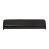
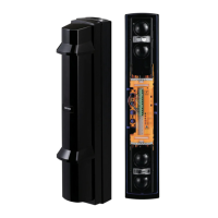
: X-ZONE T
: Black
: 6'7" to 11'6" (2.0 to 3.5 m)
: See Detection area
: Active infrared reflection (*1)
Microwave doppler effect
: 24.125 GHz
: < 20 dBm
: AIR area -6 to +6°
Microwave area +25 to +45°
: 12 to 24 VAC ±10% (50/60 Hz)
12 to 30 VDC ±10%
: < 2.5 W (< 4 VA at AC)
: See Operation indicator table
: Approx. 500 ms
: < 300 ms
: -31 to 131°F (-35 to +55°C)
: < 80%
Noise level
Activation output
Test input
Safety output
IP rate
Weight
Accessories
: < 70 dBA
: Form A relay
50 V 0.3 A Max.(Resistance load)
: Opto coupler
Voltage 5 to 30 VDC
Current 6 mA Max. (30 VDC)
: Form A relay
50 V 0.3 A Max.(Resistance load)
: IP54
: 9.5 oz (270 g)
: 1 Operation manual
2 Mounting screws
1 Mounting template
1 Area adjustment tool
1 Cable 9'10" (3 m)
1000 ms 1000 ms
Operation indicator table
Warm-up
Stand-by (Installation mode)
Status
Yellow blinking
Yellow
Operation indicator color
Signal saturation
Sensor failure
Slow Green blinking
Fast Green blinking
Stand-by (Operation mode)
2nd row detection
BLUEZONE (1st row) detection (*2)
3rd row detection
Microwave detection
Green
Orange
Red
Red blinking
Blue
Communication test output Turn off 500 ms (*3)
The specifications herein are subject to change without prior notice due to improvements.
*1 : Active infrared reflection has a presence detection function.
*2 : See BLUEZONE area
*3 : LED will be turned off approx. 500 ms when the sensor test output signal works well.
NOTE
1 1/2"(38)
2 3/8"(61 )
10 1/2"(267)
4 15/16"(125)
1 7/16"(36) 1 11/16"(43)
5/16"(7.5)
(1) Connector
(2) Mounting holes
(3) Operation indicator
(4) Width adjustment screws
(5) Depth angle adjustment screw
(6) Microwave sensitivity potentiometer
(7) Dipswitches
(8) Detection window
(9) Area adjustment tool
[inch (mm)]
(9)
(1)
(4) (5) (7)
(8)
(3)
(2)
(6)
Dimensions and part names
Motion/Presence detection
Microwave
Motion detection
NOTE
1. Mounting
H : Height from the floor to the bottom of the header
(The mounting height is "H + Y".)
Y : Distance between the bottom of the header and the sensor
X : Distance between the door and the mounting surface
NOTE
CAUTION
Risk of getting caught
Make sure to affix the mounting template as described in the above chart, otherwise it can be dangerous since there
may be no detection area around the threshold. Install the sensor as low as possible on the header.
Before starting the procedure, make sure that the power is turned OFF.
When passing the cable through the hole, do not tear the shield otherwise it may cause electric shock or breakdown of
the sensor.
2. Wiring
Danger of electric shock
WARNING
a. Plug the connector.
b. Supply power to the sensor. Adjust the detection area and set the dipswitches.
(See Adjustments 4. Dipswitch settings)
3. Turn ON the power
NOTE
Place the housing cover.
If wiring is to be exposed, break the knockout.
4. Mounting the housing cover
Do not use the sensor without the cover.
When using the cable knockout, install the sensor indoors or use the rain cover (separately available) otherwise electric
shock or breakdown of the sensor may occur.
WARNING
Danger of electric shock
The following conditions are not suitable for sensor installation.
-Fog or exhaust emission around the door
-Wet floor
-Vibrating header or mounting surface
-Moving objects, steel plate, emergency lights or illumination in the detection area or in vicinity
-Highly reflecting floor or highly reflecting objects around the door
Do not wash, disassemble, rebuild or repair the sensor, otherwise it may cause electric shock or breakdown of the
equipment.
Danger of electric shock
WARNING