EasyManua.ls Logo

Oriental motor BLE Series User Manual

Oriental motor BLE Series
52 pages
To Next Page IconTo Next Page
Page #1 background imageLoading...
Page #1 background image
HM-5109-7
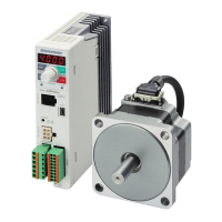
Brushless Motor and Driver Package
BLE Series
Standard type, Electromagnetic brake type
OPERATING MANUAL
Thank you for purchasing an Oriental Motor product.
This Operating Manual describes product handling procedures and safety precautions.
Please read it thoroughly to ensure safe operation.
Always keep the manual where it is readily available.
Table of contents
1 Introduction ..........................................2
2 Safety precautions ...............................4
3 Precautions for use ..............................6
4 System conguration ...........................7
5 Preparation ..........................................8
5.1 Checking the product .............................. 8
5.2 How to identify the product model ........... 8
5.3 Combination tables ................................. 9
5.4 Names and functions of parts ............... 10
6 Installation..........................................12
6.1 Installation location ................................ 12
6.2 Installation overview .............................. 12
6.3 Installing the combination parallel shaft
gearhead ............................................... 13
6.4 Installing the round shaft type ............... 14
6.5 Installing the combination type
hollow shaft at gearhead ..................... 14
6.6 Installing a load ..................................... 17
6.7 Permissible radial load and
permissible axial load ............................ 19
6.8 Installing the driver ................................ 20
6.9 Installing the regeneration unit
(accessory) ............................................ 22
6.10 Installing the external potentiometer
(supplied) .............................................. 22
6.11 Installing and wiring in compliance with
EMC Directive ....................................... 23
7 Connection.........................................25
7.1 Connection example ............................. 25
7.2 Connecting the power supply ................ 26
7.3 Grounding ............................................. 26
7.4 Connecting the motor and driver ........... 27
7.5 Connecting the regeneration unit .......... 28
7.6 Selecting the I/O signal power supply ... 29
7.7 Connecting the I/O signals .................... 29
7.8 Connecting the communication cable ... 34
7.9 Connection diagram (example) ............. 35
8 Operation ...........................................38
8.1 Operation overview ............................... 38
8.2 Basic operation ..................................... 39
8.3 Setting the acceleration time and
deceleration time ................................... 41
8.4 Changing the speed .............................. 42
8.5 Examples of operation patterns ............ 42
8.6 Parallel operation .................................. 43
8.7 Setting the
FBL
compatible mode and
operation ............................................... 44
9 Extended functions ............................47
10 Inspection ..........................................47
11 Protection function .............................48
12 Troubleshooting and remedial
actions ...............................................50
13 Accessories (sold separately) ............51
Questions and Answers:

Oriental motor BLE Series Specifications

General IconGeneral
BrandOriental motor
ModelBLE Series
CategoryEngine
LanguageEnglish

Summary

1 Introduction

Product Overview and Standards

General description, product standards, and CE marking information.

Installation Conditions

Specifies environmental and physical requirements for installation.

Safety and Compliance Directives

Covers Low Voltage Directive and initial safety notes before use.

2 Safety Precautions

Understanding Warning Symbols

Explanation of warning, caution, and note symbols and their implications.

Critical Safety Warnings

General safety instructions for proper and safe operation.

Specific Cautions and Label Information

Detailed cautions for handling and explanations of warning labels on the driver.

3 Precautions for Use

Power Line Protection and Wiring

Best practices for power line protection, including breakers and filters.

Usage Recommendations and Noise Control

Guidance on motor types, regeneration units, and noise reduction measures.

4 System Configuration

5 Preparation

Product Checking and Model Identification

Verifying product contents and understanding model nomenclature.

5.3 Combination Tables

Tables detailing motor, gearhead, and driver combinations.

5.4 Names and Functions of Parts

Description of motor and driver components and their functions.

Detailed Part Explanations

Further explanations of component names and their specific functions.

6 Installation

6.1 Installation Location

Guidelines for selecting an appropriate installation site for the motor and driver.

6.2 Installation Overview

General installation procedures for motor and driver units.

Installing Gearheads (Parallel/Hollow Shaft)

How to install different types of gearheads onto the motor.

Driver and Gearhead Installation Details

Mounting the driver and procedures for gearhead removal and installation.

6.4 Installing Round Shaft Type

6.5 Installing Hollow Shaft Gearheads (Front Mount)

Mounting hollow shaft gearheads using the front side as the mounting surface.

6.5 Installing Hollow Shaft Gearheads (Rear Mount)

Gearhead Removal and Installation Procedures

Detailed steps for detaching and attaching gearheads to the motor.

6.6 Installing a Load

Load Attachment for Shaft Types

Attaching loads to parallel and round shaft types.

Output Shafts and Coupling Methods

Description of shaft types and methods for coupling loads.

Load Attachment for Hollow Shaft Gearheads

Attaching loads to hollow shaft gearheads using specific methods.

Using Stepped and Non-Stepped Load Shafts

Methods for using different types of load shafts for secure attachment.

6.7 Permissible Radial and Axial Loads

6.8 Installing the Driver

General driver installation guidelines and methods.

Driver Mounting Methods (Screws/DIN Rail)

Installing the driver via screws or using a DIN rail mounting plate.

6.9 Installing Regeneration Unit

6.10 Installing External Potentiometer

Procedure for installing the supplied external potentiometer.

6.11 Installing for EMC Directive Compliance

Procedures for EMC compliant installation and wiring.

Mains Filter, Power Lines, and Grounding

Connecting filters, power lines, and proper grounding procedures.

Installation and Wiring Notes

Important notes regarding installation, wiring, and static electricity precautions.

7 Connection

7.1 Connection Example and Switch Settings

Illustrative connection diagram and switch configurations for operation.

7.2 Connecting the Power Supply

How to connect the AC power supply to the driver.

Circuit Breaker and Grounding

Requirements for circuit breakers and motor grounding.

Driver Grounding and Motor/Driver Connection

Grounding the driver and connecting motor/driver cables.

Connection Cables and Regeneration Unit

7.5 Connecting the Regeneration Unit

Wiring the accessory regeneration unit.

7.6 Selecting I/O Signal Power Supply

Choosing the power source for I/O signals.

7.7 Connecting I/O Signals

Wiring the input/output signals to the driver.

I/O Connector Functions

Details of I/O signal connector pin assignments.

Understanding Input Signals

MB-FREE and TH Input Signals

Specific input signal functions like brake release and thermostat input.

Understanding Output Signals

Explanations of output signals like SPEED-OUT and ALARM-OUT1.

Controller with Clamp Diode Considerations

Considerations for controllers with clamp diodes during connection.

I/O Signal Circuit Examples (Sink/Source Logic)

Diagrams for sink and source logic I/O connections.

7.8 Connecting Communication Cable

7.9 Connection Diagram (Sink Logic Example)

Example connection diagram using sink logic with built-in power supply.

Connection Diagram (External Power Supply Example)

Example connection diagram using external power supply.

Connection Diagram (Source Logic Example)

Example connection diagram using source logic.

8 Operation

8.1 Operation Overview

Summary of available operation types: basic, FBL II compatible, and extended.

8.2 Basic Operation

Core operational functions including motor run/stop and speed setting.

Speed Setting Methods

How to set the motor speed using internal potentiometer, external potentiometer, or DC voltage.

Motor Running and Stopping

Controlling motor start and stop using operation control signals.

8.3 Setting Acceleration and Deceleration Time

8.4 Changing Motor Speed Between Two Levels

Operating the motor at two different speeds using M0 input.

8.5 Operation Pattern Examples

Illustrative examples of motor operation sequences with timing charts.

8.6 Parallel Operation

Operating multiple motors simultaneously at the same speed.

Parallel Operation Setup (Potentiometer/DC Voltage)

Setup for parallel operation using external controls.

8.7 Setting FBL II Compatible Mode

FBL II Mode Details and Comparison

Comparing FBL II and BLE series features and operation modes.

FBL II Operation Control and Speed Characteristics

Control logic and speed characteristics specific to FBL II compatible mode.

FBL II Operation Pattern Example

Example operation pattern demonstrating FBL II mode capabilities.

9 Extended Functions

Extended Functionality with OPX-2A/MEXE02

Features available via external tools like speed setting, torque limit, and data copy.

10 Inspection

Regular Inspection Items

Recommended checks for motor and driver to ensure proper operation.

11 Protection Function

Alarm Flashing Patterns and List

Understanding alarms via LED blinking and the comprehensive alarm list.

Alarm Remedial Actions

Steps to resolve identified alarms by addressing causes and resetting.

12 Troubleshooting and Remedial Actions

Troubleshooting Motor Operation Issues

Diagnosing and fixing problems related to motor operation.

Troubleshooting Direction, Speed, and Stability

Addressing issues with incorrect rotation, speed, or unstable operation.

Troubleshooting Stopping and Brake Issues

Resolving problems with motor stopping and brake engagement.

13 Accessories (Sold Separately)

Connection Cables and Regeneration Unit

Details on various connection cables and the regeneration unit.

Speed Indicator, Data Setter, and Software Cable

Information on optional accessories like speed indicators and data setters.

DIN Rail Mounting Plate

Accessory for mounting the driver onto a DIN rail.

Related product manuals