5
3. Ports Introduction
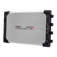
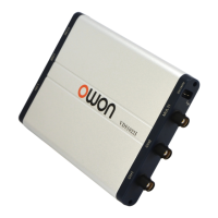
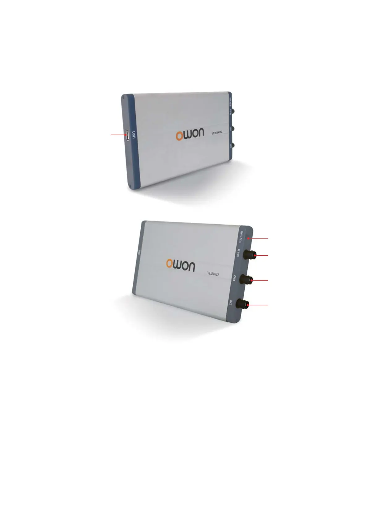
VDS1022(I)
Figure 3-1 Ports of the Oscilloscope
1. USB port: Supply power by PC USB or the adapter; communicate with PC
2. Probe Compensation: Measurement signal (3.3 V / 1 kHz) output
3. MULTI port: EXT trigger input, trigger output or Pass/Fail output
4. Signal input of Channel 2
5. Signal input of Channel 1
 Loading...