TM7050-EI00 | 03/2017
PARADOX.COM
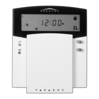
TM70 (7”) / TM50 (5”) Touchscreen Keypads
Installation Manual
Installation
WIRING: For the TM70 it is
recommended
to use 18 gauge wire unless wire feed
one keypad and distance is less than 100ft./30m.
TM50 we recommend 18 gauge as well, however, 22 gauge can be used up to 150ft.
Feeding wire (bus) should not have more than 1.0V drop, each TM70 rep-
resents 0.3A max current, and TM50 150mA, wire resistance calculator can be
found on the web. Resistance per:100ft 22 gauge wire = 1.6 Ohm, 18 gauge
0.64 Ohm. Voltage drop formula:
V = 2R x 0.3N (TM70), V = 2R x 0.15N (TM50)
R = Wire resistance, N= Number of TM70s fed by the wire, use lower gauge
wire if necessary.
Tab
Location
Tab
Location
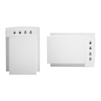
1. Separate the top assembly from the
back plate. Insert a flathead screw-
driver into the tab located, as shown
in Figure 1.
2. Mount the back plate to the wall or to
a gang box using appropriate screws.
Ensure that the UP arrow on the back
plate is in the up position.
Note: We recommend to feed
the TM70 with 18 gauge wire.