10
Parker Hannifin
Pump and Motor Division
Trollhättan, Sweden
Service Manual
Series F11
Bulletin HY30-5503-M1/UK
Reassembly, Series F11-5 through
-150
All parts should be thoroughly cleaned and lightly lubricated
with hydraulic fluid. Reassembly is carried out in reverse
order of disassembly.
Caution: Follow directions for use of hydraulic fluid carefully.
Protect your hands and eyes from fluid. Fluid may also be
flameable.
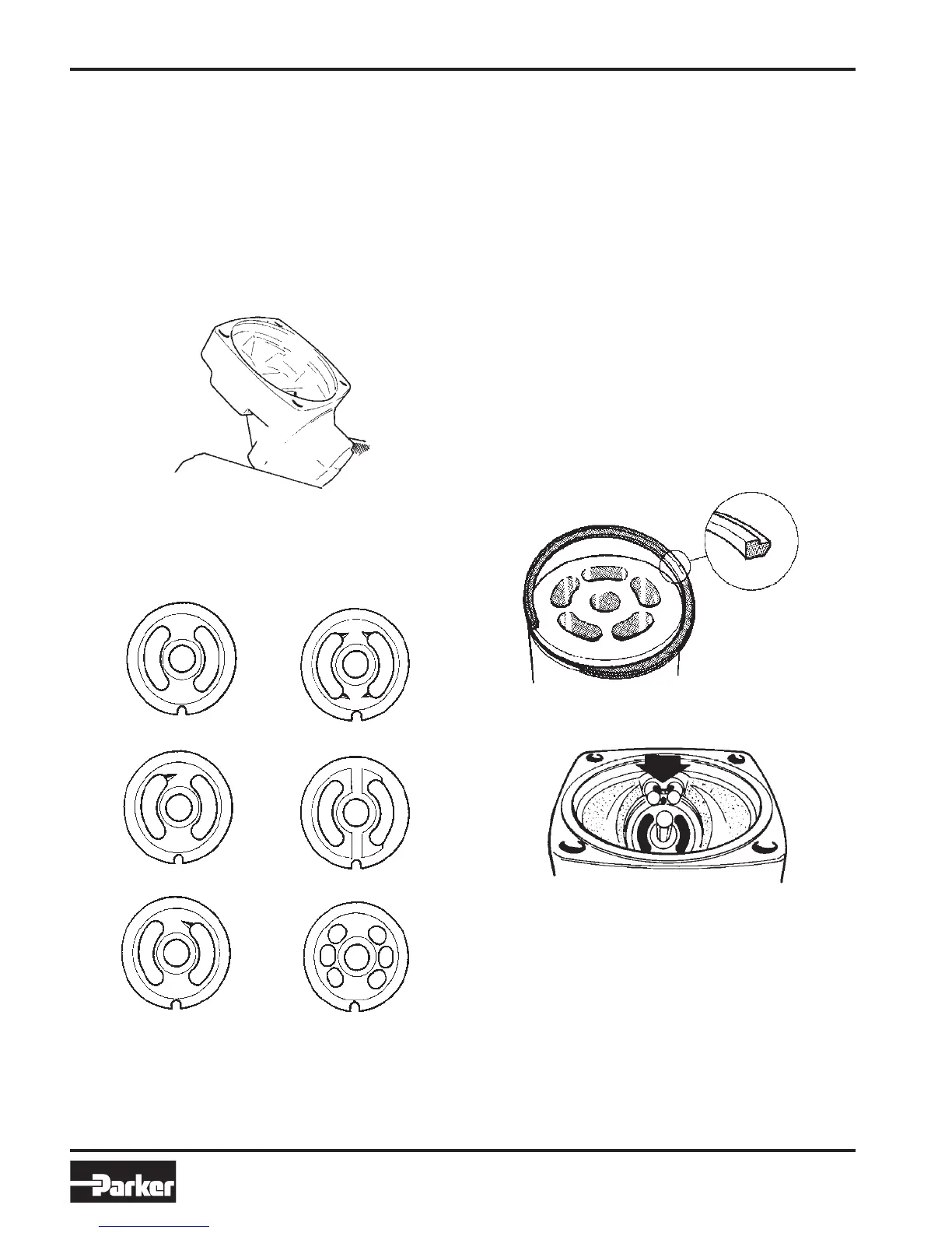
The internal drain valve plate G is shown from the back side
of the plate. From the front, when installed, it looks the same
as the M plate.
The following valve plates are available (designation ap-
pears on the nameplate):
M = Bi-directional, motor or pump operation
L = L.H. rotation, pump operation
R = R.H. rotation, pump operation
G = L.H. rotation, internal drain, motor operation
J = R.H. rotation, internal drain, motor operation
H = Bi-directional, motor operation, high pressure
Q = Bi-directional, motor operation, low noise
3. The cylinder barrel retaining ring (does not apply
to Series F11-28 and -58) should be installed as
illustrated below. When installing the barrel in the
housing, the opening of the retaining ring should face
the housing cut-out as shown; the barrel has to be
pushed down to overcome the spring force of the
retaining ring.
Some resistance should be felt when trying to turn
the cylinder barrel by hand; if no resistance is felt, the
retaining ring must be replaced.
Note
Regarding installation of needle bearings in
F11-110 and -150 cylinder barrels, refer to
page 16.
4. Series F11-28 and -58 utilize a leaf spring for bar-
rel hold-down. Install the cylinder barrel on the barrel
post, install the hold-down ring and the leaf spring,
and secure the spring with the locating pin.
Drain port
M
L
R
Q
G
H
2. Install the valve plate making sure it is seated
properly in the housing; when installed correctly,
the visible face of the valve plate should appear as
shown.
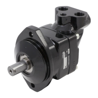
1. Place the cylinder barrel housing in a vice as
shown.
 Loading...