© 2010 - 2020 Persistent Systems, LLC – All Rights Reserved
PAGE 36 OF 176
The export and/or the release of certain products, technology and software to non-US persons might
be subject to export restrictions. Please refer to the US export laws & regulations for details.
PHYSICAL SETUP: SIDE CONNECTORS
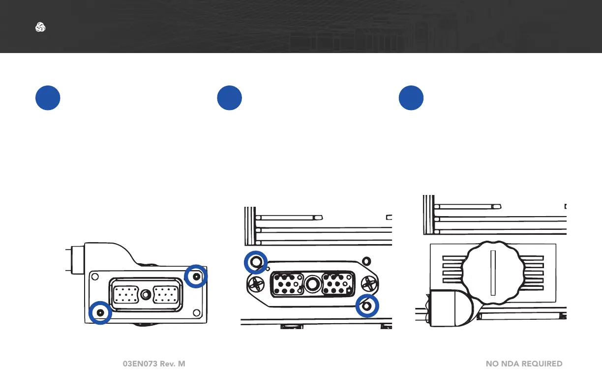
1
The 22-Pin connector on
every cable is keyed so
that it will only attach to
a compatible side con-
nector. If a cable can
attach to multiple side
connectors, it is keyed
(or not keyed) so that it
will attach to all compati-
ble side connectors.
2
To connect a cable to a
side connector, locate
the appropriate side
connector.
3
Align the key pins on
the 22-Pin connector
with the key holes on
the case. Push the key
pins into the key holes.
Connecting a Cable to a Side Connector

 Loading...