Fuel vapour recirculation system
14 This system has been introduced
progressively on all fuel injection models, and
prevents fuel vapour from the fuel tank from
being ejected into the atmosphere (see
illustration).
15 The fuel filler cap is sealed, and the fuel
vapours from the tank pass into a carbon
canister, via a calibrated orifice and a pipe.
The fuel vapour is absorbed by the carbon
filling in the canister.
16 When the engine is running, it draws a
proportion of its inlet air through the carbon
canister, and this air picks up the fuel vapour
contained in the carbon canister.
17 A solenoid valve mounted in the pipe
between the canister and the inlet manifold
prevents the system from operating when the
engine is cold. The solenoid valve is
controlled by the electronic control unit, on
the basis of information received from the
coolant temperature sensor.
2 Exhaust system - removal
and refitting
2
Removal
1 Details of exhaust system routing and
mounting will vary with model and year, but
the principles of removal and refitting remain
the same (see illustration).
Exhaust and emission control systems 4D•3
4D
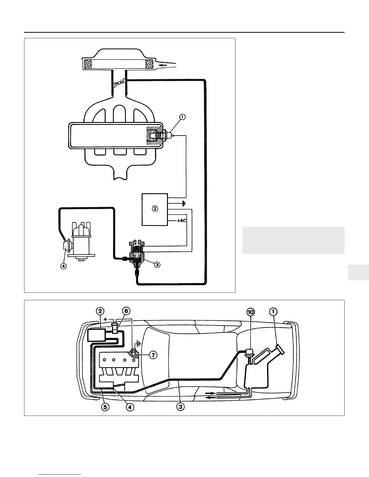
1.9 Electro-pneumatic ignition timing
retarding system
1 Coolant temperature sensor
2 Electronic control unit
3 Solenoid valve
4 Distributor vacuum capsule
1.14 Fuel vapour recirculation system
1 Fuel filler cap
2 Charcoal canister
3 Hose
4 Calibrated orifice
5 Hose
6 Solenoid valve
7 Coolant temperature sensor
10 Safety valve
 Loading...