MINI MCR-SL-UI-UI
101945_en_05 10
PHOENIX CONTACT GmbH & Co. KG • 32823 Blomberg • Germany
www.phoenixcontact.com
8Adjustment
A potentiometer is located underneath the cover; this is used
for fine adjustment of the analog signals once the configura-
tion of the DIP switches has been modified.
The module is adjusted via its output final value:
• Connect the calibration source to the input of the isolating
amplifier and specify the final value of the set input signal.
• Use the potentiometer to set the exact final value of the
set output signal.
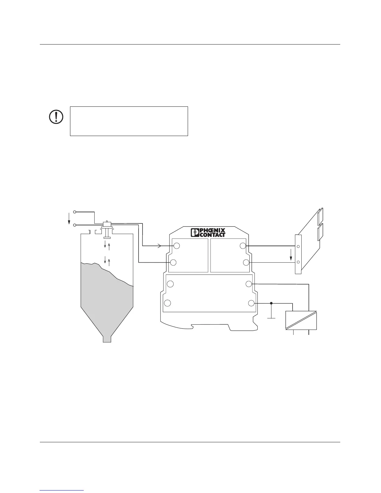
9 Connection/application example
Figure 6 Example application
Once the configuration of the DIP switches has
been modified, the potentiometer allows the
accuracy to be increased from < 0.4% to <
0.1%.
 Loading...