corresponding terminal; for this purpose it is al-
ways advisable to consult the electrical circuit
diagrams.
KEY:
1 = Red (direct current)
2 = White (direct current)
3 = Grey - Red (direct current)
4 = Purple (alternating current engine stop)
5 = Black (ground)
6 = White - Red (direct current)
7 = Grey (direct current)
8 = Black
* = Connection connected to the red cable of the condenser charging coil.
** = Connections with electronic ignition.
For obvious reasons it is essential that, in case of
replacement of one or more devices in the system
(main switch, stator unit of the flywheel, control
unit) during reassembly, a device is used that is
similar to the existing one: if in fact similar devices
were used, but not specific to the same ignition
system, they would not work, risking irreparable
damage to the control unit.
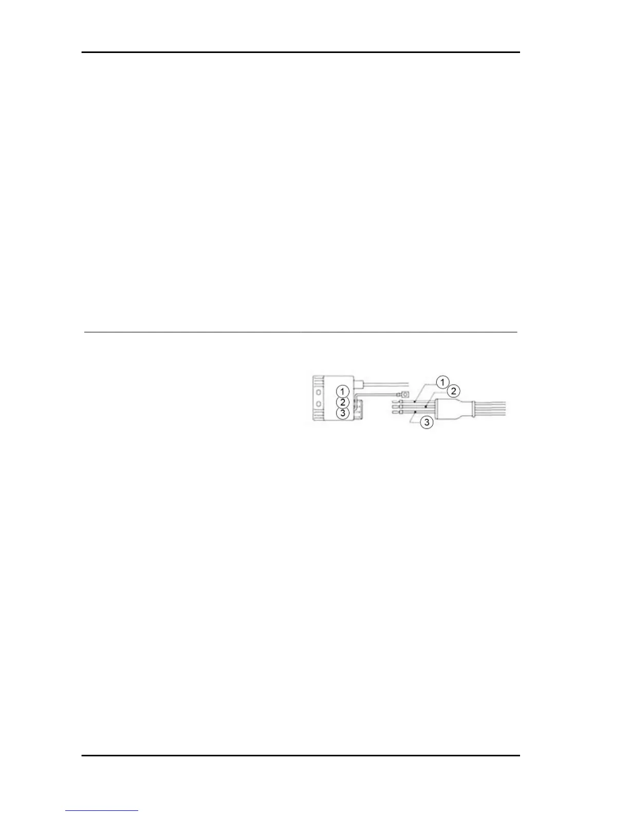
KEY:
1 = White
2 = Red
3 = Green
B) INSPECTIONS TO BE PERFORMED IN THE EVENT OF IGNITION IRREGULARITIES
In the event of failure and abnormal operation of the ignition, whose causes are not detectable by a
visual inspection, it is necessary first to replace the control unit with a corresponding, safely functional
one. Remember that the disconnections and connections to replace the control unit must be performed
when the engine is off.
General guidelines APE TM Benzina
GEN - 8

 Loading...