32
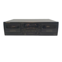
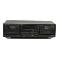
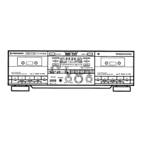
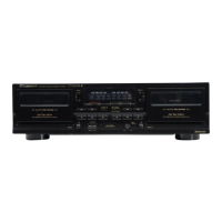
CT-W208R
• The information shown in the list is basic information and may not correspond exactly to that shown in the schematic diagrams.
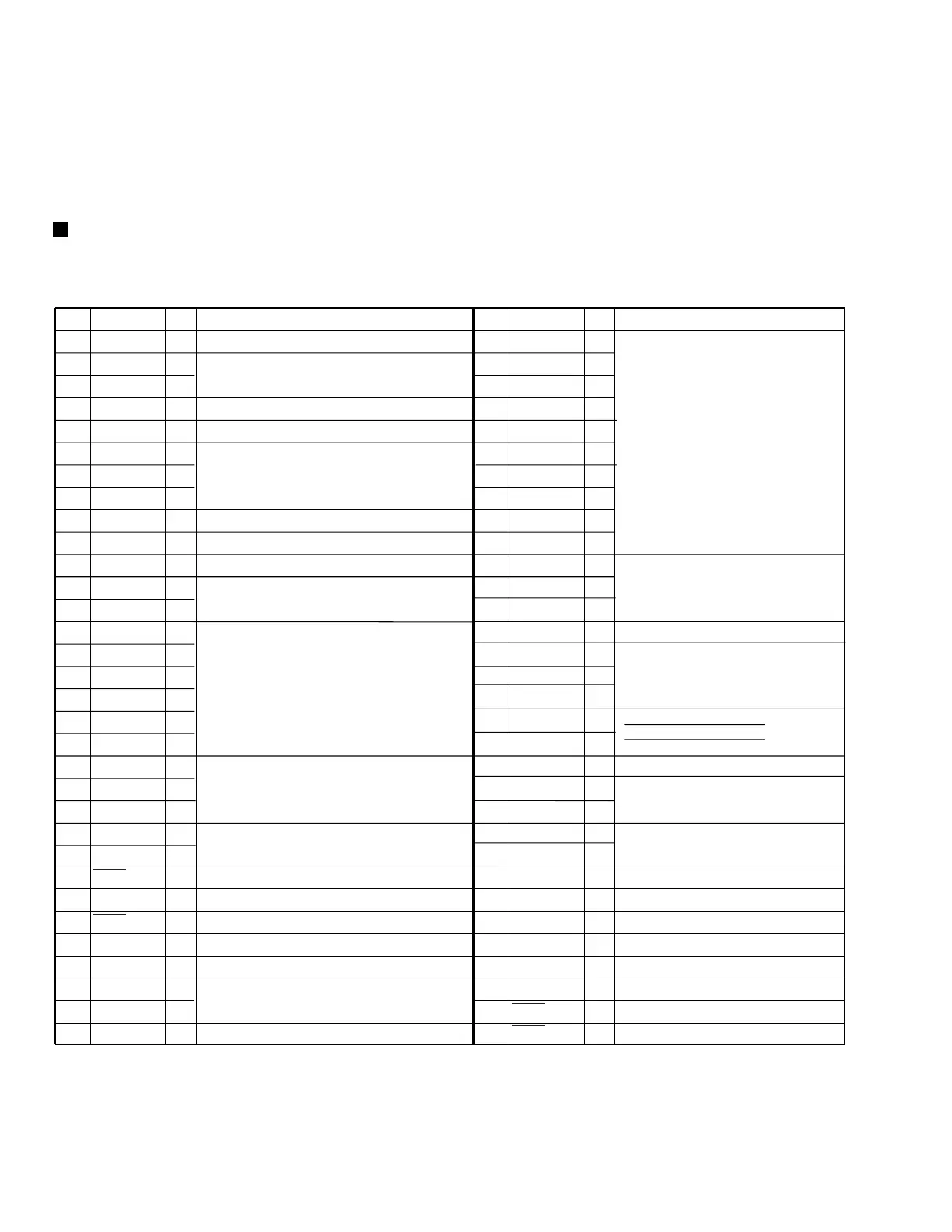
PD5351A (MAIN UNIT : IC501)
• U-COM IC
•
Pin Function
7.2 PARTS
7.2.1 IC
No. Pin Name I/O Pin Function No. Pin Name I/O Pin Function
1 VCC I Power supply 5V
34 SLD4
O
2 AREF I AREF is connected to 5V
35 SLD3
O
3 AVSS I AVSS is connected to GND.
36 SLD2
O
4 METL I L ch level meter input
37 SLD1
O
Display output
5 METR I R ch level meter input
38 SLD0
O
(Soft scanning output)
6 KEY2 I
39 GLD3
O
7 KEY1 I Key scanning input (Key switch A/D input)
40 GLD2
O
8 KEY0 I
41 GLD1
O
9 SEN1 I Take-up side sensing puise.Primary side input
42 GLD0
O
10 SEN2 I
43 OKY2
O
11 SW0 O
44 OKY1
O
Output for detecting Dolby NR SW,
12 DOLO O
45 OKY0
O
REVRS SW.
13 DOLB O
46 PD
O
Connected to a pull-down ressistor.
14 MOD2 I
47 CDSY
I
CD SYNCHRO input/output
When SYNCHRO jack IN, "L" input.
During CD play, "L" input. When
SYNCHRO REC, TOCD is output in "H".
15 CRO2 I Mechanical SW input voltage
48 FRCD I
16 HAF2 I "L" when all the following SWs are ON.
49 TOCD
O
17 FRC2 I Mode SW, chrome SW, half SW,
50 TP1
O
18 MET2 I forward record disable SW, metal SW,
51 TP0
O
NOR CRO MET
TP0 L H L
TP1 L L H
19 RRC2 I reverse record disable SW.
52 X1
O
20 MOD1 I "L" when all the following SWs are ON.
53 SOL1
O
Deck 1 side mechanical control output
Solenoid control
Capstan motor control
Deck 2 side mechanical control output
Solenoid control
Capstan motor control
Motor speed adjustment. When X1, "H"
21 CRO1 I Mode SW, chrome SW, half SW.
54 CPM1
O
22 HAF1 I
55 SOL2
O
23 VLED I Power supply SW version select input.
56 CPM2
O
24 VTAC I Power SW Without LED VTAC: L, VLED: L.
57 MRCV
O
Meter circuit recovery time control.
25
REMT
I Remote commander signal input
58 MGAN Meter circuit gain select. (When MS, "H")
26 NVSS I Chip operation mode control. Connected to GND.
59 PBNR When a normal tape is played back, "H"
27
REST
O Reset signal input. ("L" when reset.)
60 2PB
O
O
O
When deck 2 is played back, "H"isoutput
28 POFF I Power off signal input. ("H" when power off.)
61 DEC
O
DECODE/ENCODE output.
29 PD O Connected to pull-down resistor.
62 BIAS
O
BIAS control.(When bias ON, "H".)
30 XIN I
Connected to the main clock (6.3 MHz)
63
RMUT
O REC MUTE control. (When MUTE "L".)
31 XOUT O
64
LMUT
O
LINE MUTE control. (When MUTE "L".)
32 VSS I Power supply GND
33 SLD5
Take-up side sensing puise.Secondary side input
DOLBY NR SW, REVERS SW DC input
DOLBY NR control When Dolby NR OFF,
DOLO:"H". When Dolby NR B, DOLB: "H".
H:5V
L:GND
O
 Loading...