5
En
INPUT
PHONO CD TUNER
L
R
GND
IN
OUT
L
R
FM
UNBAL
75Ω
AM
LOOP
ANTENNA
ANTENNA
CONTROL
OUTPUT
220V
240V
110V
120 - 127V
220 - 240V
110 - 127V
TWO VOLTAGE SERECTORS
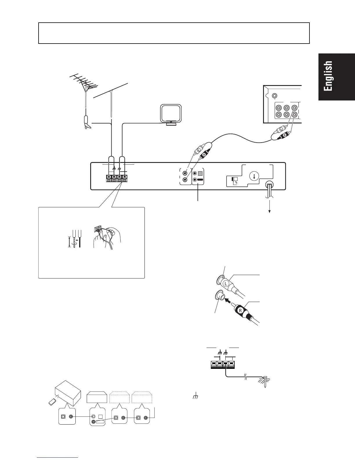
CONNECTIONS
CONTROL terminals
When using together with a Pioneer component bear-
ing the Î mark, connect the CONTROL IN terminal on
the rear panel of the tuner to the CONTROL OUT termi-
nal on the component using the supplied control cord.
This will enable the tuner to be controlled from a dis-
tance with the remote control unit supplied with the
component.
When this feature is not used, connection is not neces-
sary.
¶ For instructions regarding connection and operation,
please refer to the operating instructions of your ste-
reo component.
Before making or changing the connections, switch off
the power switch and disconnect the power cord from
the AC outlet.
CONTROL
IN
OUT
CONTROL
IN OUT
CONTROL
IN OUT
CD Player
Cassette Deck
CONTROL
IN
OUT
Stereo
Amplifier
Outdoor FM
antenna
Stereo amplifier
Plug the power cord
into an ACwall socket.
Accessory AM loop antenna
Accessory FM T-type antenna
CONTROL terminals
Connecting the FM T-type antenna
and AM loop antenna
15 mm
1. Strip and twist the ends of the wires.
2. With tabs beneath connector down, insert
wires from antenna.
Accessory
Audio cord
Pin plug connecting cord
¶ Connect the white plug to the white terminal (L) and
the red plug to the red terminal (R).
¶ Make sure that the connections are secure.
Left channel
Right channel
White plug
Red plug
NOTE:
The (signal earth) helps reduce noise when an antenna
is connected. It is not a safety earth.
Antenna ground
CAUTION:
Never make the ground connection to a gas pipe as sparks
can cause the gas ignite.
FM
UNBAL
75Ω
AM
LOOP
ANTENNA
ANTENNA
F-208
 Loading...