4.2
1C
DESCRIPTIONS
4.2.1 CXA1082AS
FOCUS SERVO SYSTEM
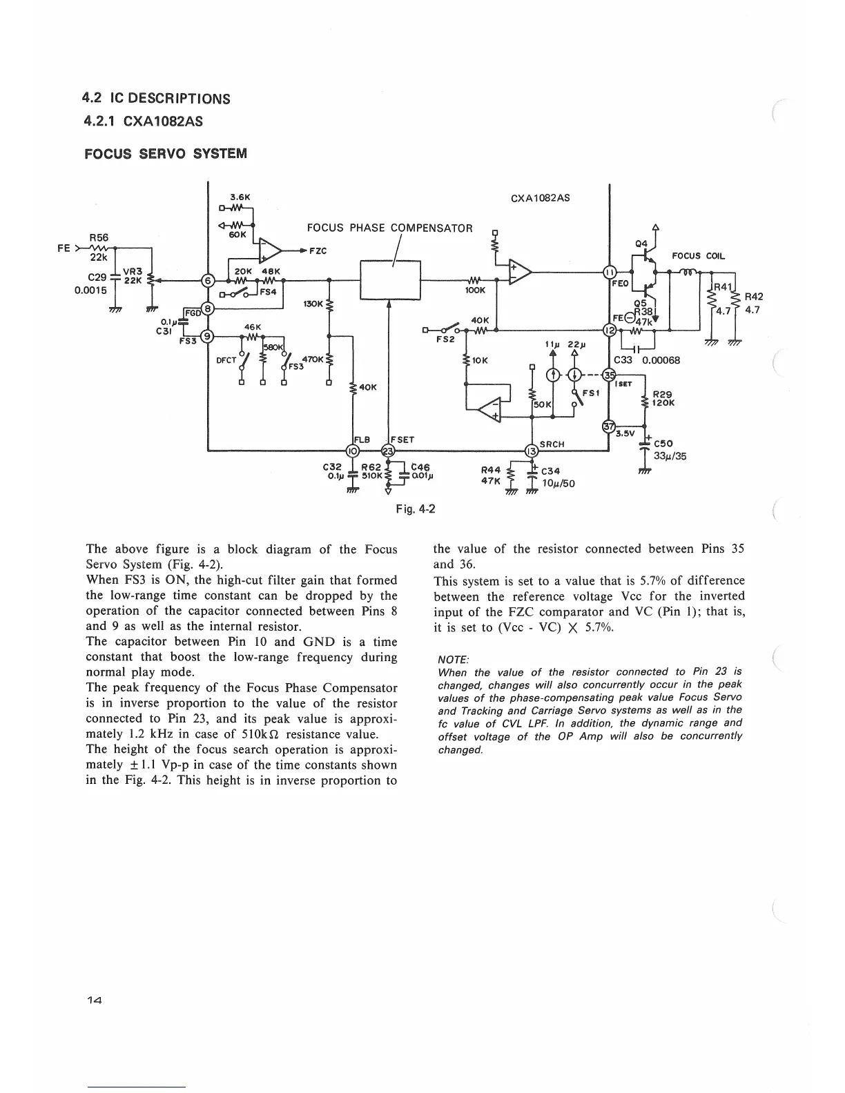
The above figure is a block diagram of the Focus
Servo System (Fig. 4-2).
When FS3 is ON
9
the high-cut filter gain that formed
the low-range time constant can be dropped by the
operation of the capacitor connected between Pins 8
and 9 as well as the internal resistor.
The capacitor between Pin 10 and GND is a time
constant that boost the low-range frequency during
normal play mode.
The peak frequency of the Focus Phase Compensator
is in inverse proportion to the value of the resistor
connected to Pin 23
9
and its peak value is approxi-
mately 1.2 kHz in case of 510kn resistance value.
The height of the focus search operation is approxi-
mately ±1.1 Vp-p in case of the time constants shown
in the Fig. 4-2. This height is in inverse proportion to
the value of the resistor connected between Pins 35
and 36.
This system is set to a value that is 5.7% of difference
between the reference voltage Vcc for the inverted
input of the FZC comparator and VC (Pin 1); that is
9
it is set to (Vcc - VC) X 5.7%.
NOTE:
When the value of the resistor connected to Pin 23 is
changed, changes will also concurrently occur in the peak
values of the phase-compensating peak value Focus Servo
and Tracking and Carriage Servo systems as well as in the
fc value of CVL LPF. In addition, the dynamic range and
offset voltage of the OP Amp will also be concurrently
changed.
14
 Loading...