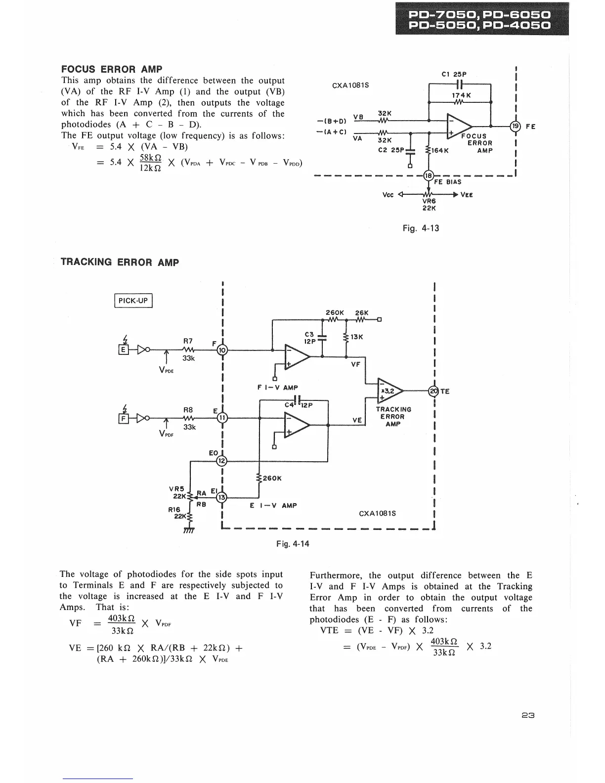
FOCUS ERROR AMP
This amp obtains the difference between the output
(VA) of the RF I-V Amp (1) and the output (VB)
of the RF I-V Amp (2), then outputs the voltage
which has been converted from the currents of the
photodiodes (A + C - B - D).
The FE output voltage (low frequency) is as follows:
VFE = 5.4 X (VA - VB)
58kl2
12kn
- 5.4 X
X (VPDA + VPDC - V ,
VPDD)
Fig.
4-13
TRACKING ERROR AMP
Fig.
4-14
The voltage of photodiodes for the side spots input
to Terminals E and F are respectively subjected to
the voltage is increased at the E I-V and F I-V
Amps. That is:
403k a
VF =
33k«
X V
P
,
VE =[260 kfi X RA/(RB + 22k
12)
+
(RA + 260kfi)]/33kO X V
PDE
Furthermore, the output difference between the E
I-V and F I-V Amps is obtained at the Tracking
Error Amp in order to obtain the output voltage
that has been converted from currents of the
photodiodes (E - F) as follows:
VTE = (VE - VF) X 3.2
403k n
= (VP
VPDF)
X
33kO
X 3.2
23
 Loading...