EasyManuals Logo

Pioneer YN009GMFI22RPD User Manual

Pioneer YN009GMFI22RPD
145 pages
To Next Page IconTo Next Page
To Previous Page IconTo Previous Page
Page #95 background imageLoading...
Page #95 background image
92
Index 1:
1
. Indoo
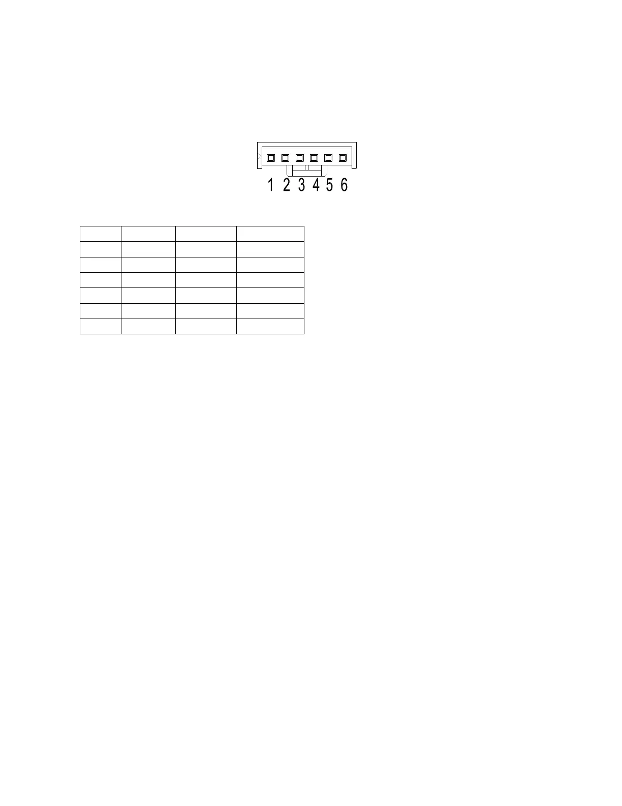
r DC fan motor(control chip is inside fan moto
r)
Power
on and when the unit is in standby, measure the voltage of pin1-pin3, pin4-pin3 in fan moto
r
conn
ector. If the value of the voltage is not in the range showing in below table, the PCB must h
ave
p
roblems and need to be replaced.
DC
motor voltage input and output
NO. Color Signal Voltage
1 Red Vs/Vm 200~380V
2 --- --- ---
3 Black GND 0V
4 White Vcc 13.5~16.5V
5 Yellow Vsp 0~6.5V
6 Blue FG 13.5~16.5V

Table of Contents

Other manuals for Pioneer YN009GMFI22RPD

Questions and Answers:

Question and Answer IconNeed help?

Do you have a question about the Pioneer YN009GMFI22RPD and is the answer not in the manual?

Pioneer YN009GMFI22RPD Specifications

General IconGeneral
BrandPioneer
ModelYN009GMFI22RPD
CategoryAir Conditioner
LanguageEnglish

Related product manuals