24
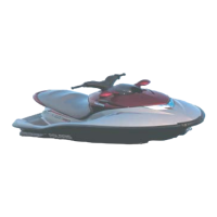
FEATURES AND CONTROLS
1. Starter Button - Depress and hold the starter but-
ton to start the engine. Release it as soon as the engine
starts. Do not depress for more than ten seconds at a
time.
NOTE: The lanyard and lock plate must be attached
to the engine stop switch to start the engine
2. Stop Switch/Lanyard - Push this switch down or
disconnect the lanyard plate to stop the engine quickly.
3. Safety Lanyard Wrist Cord - The lock plate end is
attached to the stop switch. The wrist band is attached to
the operator’s wrist or PFD.
4. GaugeModeButton- This button operates the
display change for the NGI. See page 29.
5. Throttle - Squeeze the throttle lever toward the
handlebar to increase speed. Release the lever to slow
the craft and return the engine to idle.
6. Instrumentation - Instrumentation is Next Gen-
eration Instrument (NGI). See pages 29-31.
7. Seat Latch - The seat latch secures the seat in posi-
tion. When released, it provides access to the engine
compartment.
8. Jet Pump Outlet Nozzle - The nozzle is the exit for
thejet output. Orientationis controlled by the handlebars
and determines the direction of craft movement.
9. Exhaust Outlet
10. Reverse Gate
11. Drain Plugs - When water gets into the bilge, it can
be drained through the drain plugs. Remove the water-
craft fromthe waterbeforedrainingthe bilge. Be surethe
plugs are securely installed before launching the craft.
12. Fuel Tank Fill - The fuel fill is located under the
front hood.
13. Oil Fill/Dipstick - The oil fill/dipstick is located
on the oil reservoir, which is under the seat in the en-
gine compartment.
14. Jet Pump Intake Grate - The grate protects the
impeller and drive shaft and protects riders from con-
tact with components.
15. Drive Shaft - Beneath the intake grate, the drive
shaft transmits power from the engine to the impeller.
16. Ride Plate - The ride plate covers and protects the
jet pump and provides leveling control for the craft.
https://www.boat-manuals.com/
 Loading...