40
TEMPERATURES (CONT)
DESCRIPTION/ACTION DISPLAY
• Differential - Adjustable user setting that changes the tank
temperature differential with a range of 2° to 20°F. The factory
setting is 8°F.
• Tank Probe Offset - adjustable user setting, range -5° to +5°F
(factory setting 0°F).
NOTE: These settings should only be used if the hot water supply
temperature varies greatly from the Operating Set Point setting.
The Tank Probe Offset is used to calibrate control system
temperature sensing. This can improve the precision of
temperature control in the storage tank and at points of use.
This feature can also be used to compensate for building
recirculation loops (hot water returning to the storage tank) that
may cause the heating cycles to terminate prematurely.
Example: If the current sensed temperature from a
temperature probe is 120°F (49°C) and the Offset setting is
adjusted to a value other than 0°F, the control system would
calibrate or “offset” the sensed temperature from the probe
and the averaged tank temperature. Heating cycles would
be activated and deactivated based on the calibrated (offset)
temperature. A -5°F setting results in +5°F hotter water.
These settings are adjusted in the same way described for
Operating Set Point And Differential Adjustment on page 39
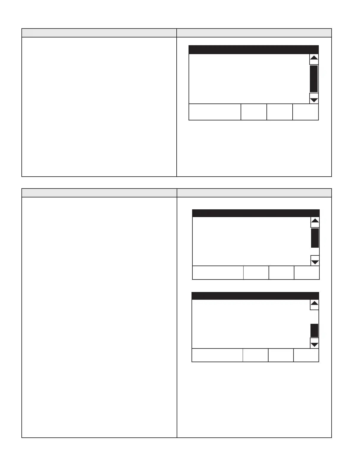
Temperatures
HELPBACK
Operating Setpoint 120°F >
Differential 8°F >
Tank Probe Offset 0°F >
HEATER STATUS MENU
DESCRIPTION/ACTION DISPLAY
Press Heater Status from the Main Menu to enter this menu. This
menu contains non adjustable operational information. Use the
slidebar to navigate the menu.
• Status - displays the current Operating State, see Table 13
on page 38.
• ECO Contact, Blocked Inlet PS, Blocked Outlet PS -
displays the current state of the switch contacts; open or
closed.
• Igniter On, Gas Valve On - displays whether or not the
control system is currently energizing these water heater
components; yes = energized, no = de-energized.
• Flame Detected - displays whether or not the control system
has detected Main Burner ame during ignition from the
ame sensor.
• Blower RPM CMD - displays the controls commanded
blower RPM.
• Blower RPM - displays the actual blower RPM.
NOTE: The menu display is shown with the Enable/Disable
switch in Enabled position and the water heater is in Standby
mode. When the Enable/Disable switch is in the Disabled
position, the water heater will be in “Water Heating Disabled”
mode.
NOTE:
The menu displays shown are for informational
purposes only. The actual heater display will vary dependent
upon the operational state of the water heater.
Top of Menu
Heater Status
HELPBACK
Status: Standby
ECO Contact Closed
Blocked Inlet PS Closed
Blocked Outlet PS Closed
Igniter On No
Bottom of Menu
HELPBACK
Gas Valve On No
Flame Detected No
Blower RPM CMD 0
Blower RPM 0
 Loading...