3 - 8
Hardware Installation Guide for the Polycom SoundStructure C16, C12, C8, and SR12
Audio Connections
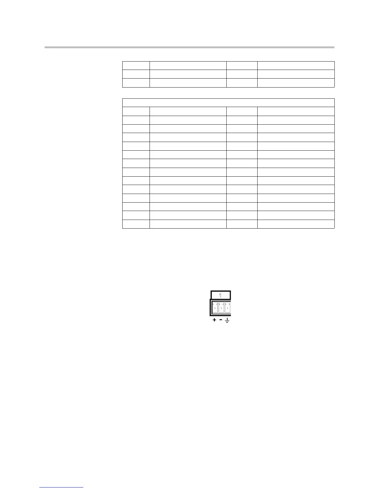
SoundStructure devices provide balanced audio input and output connections
that are terminated with 3.5 mm terminal blocks as shown in the following
figure.
For each balanced analog input or output on the SoundStructure rear-panel,
the first pin should be connected to the positive signal, the second pin is
connected to the negative signal, and the third pin is chassis ground as shown
in the balanced audio connections in the following figure. To connect the
11 Logic Output 10 24 Logic Input 11
12 Logic Output 11 25 Ground
13 Analog Gain 1
Remote Control 2
Pin Signal Pin Signal
1 +5 V 14 Logic Input 12
2 Logic Output 12 15 Logic Input 13
3 Logic Output 13 16 Logic Input 14
4 Logic Output 14 17 Logic Input 15
5 Logic Output 15 18 Logic Input 16
6 Logic Output 16 19 Logic Input 17
7 Logic Output 17 20 Logic Input 18
8 Logic Output 18 21 Logic Input 19
9 Logic Output 19 22 Logic Input 20
10 Logic Output 20 23 Logic Input 21
11 Logic Output 21 24 Logic Input 22
12 Logic Output 22 25 Ground
13 Analog Gain 2
1

 Loading...