5
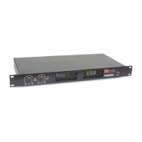
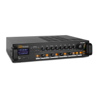
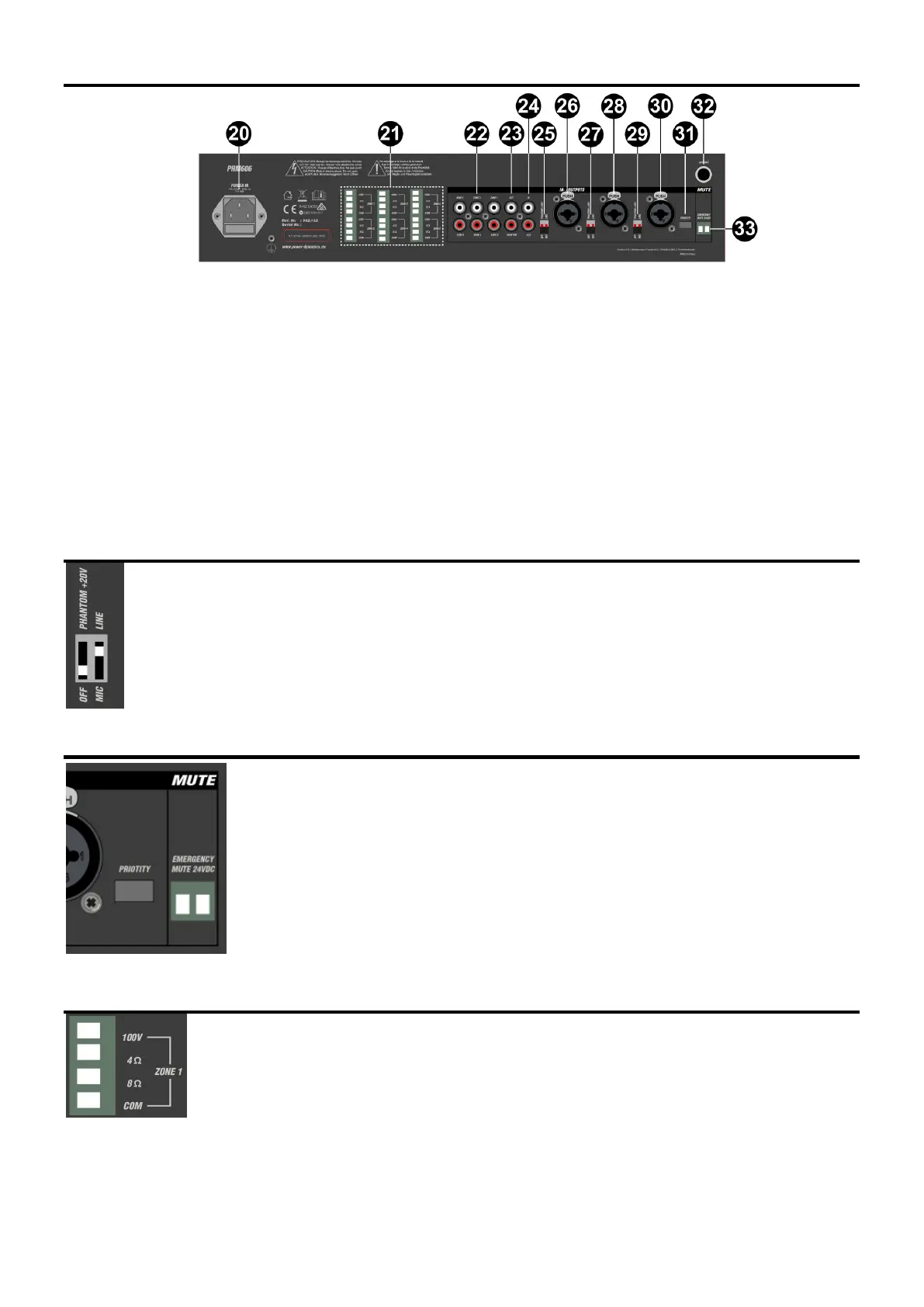
REAR PANEL
20. IEC Mains power inlet
21. Zones 1-6 speaker outlet terminals
22. Zones 1-6 line level outputs (RCA)
23. Monitor line output (2x RCA)
24. Channel 4 Aux input (2xRCA)
25. Channel 3 DIP switch adjustment (mic or line + Phantom power 20V on/off)
26. Channel 3 Mic/Line input (XLR or Jack)
27. Channel 2 DIP switch adjustment (mic or line + Phantom power 20V on/off)
28. Channel 2 Mic/Line input (XLR or Jack)
29. Channel 1 DIP switch adjustment (mic or line + Phantom power 20V on/off)
30. Channel 1 Mic/Line input (XLR or Jack)
31. Channel 1 priority switch
32. FM Antenna connection
33. 24Volt Emergency mute contacts
DIP SWITCHES
Mic/Line inputs 1, 2 and 3 each have 2 DIP switches on the rear panel (25, 27, 29) to set the input level and/or
activate +20V phantom power for use with condenser microphones.
Set the level correctly for the type of input source connected (Mic or Line)
If the source connected is a condenser microphone which requires phantom power, make sure that the phantom is
switched on for that channel.
Be sure to make these DIP switch settings when the amplifier is switched off. Making any changes when the
amplifier is powered up may cause loud bangs through the system which can damage the speakers.
PRIORITY AND EMERGENCY ACTIVATION
The Mic/Line 1 input also has a Priority switch (31), which attenuates all other channels when
Mic/Line 1 signal is detected and returns them to normal when Mic/Line 1 signal is silent.
For buildings with a main emergency alarm panel (for fire alerts etc.), the PRM606 has Mute
contacts on the rear panel (33), which will mute all audio except for channel 1 when activated by a
24V trigger voltage.
This leaves channel 1 active for evacuation announcements in the case of an emergency.
The screw terminal plug can be pulled out to make connection easier. 2-core bell wire is appropriate
for this.
Connect a 24Vdc output from the alarm control panel observing the correct polarity shown on the
contacts.
SPEAKER OUTPUTS
The PRM606 has a separate speaker output for each zone, connected via 3 large modular terminal plugs.
Each plug can be removed from the rear panel for convenient connection of speaker outputs to 2 zones.
Each zone output can be used to power either 100V line speakers or standard low impedance speakers.
These 2 configurations cannot be used together, so it is important to decide which will be used at the start.
 Loading...