5). Connect the four wires of the light and the antenna to the PCB terminals and place the wires into the conduit if
necessary. See
Figure 3.3.3 (5)
.
6). Tighten the four screws back on the light base.
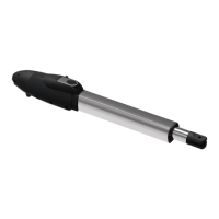
Figure 3.3.3 (6)
7). Replacing the bulb set. See
Figure 3.3.3 (7)
7.1) Unscrew the flashing light wires from the PCB terminals and make sure the power of the light is off.
7.2) Release the three screws (A)、(B)、(C) of the flashing light cover.
7.3) Separate the flashing light cover and replace the bulb set with a new one.
7.4) Tighten the three screws (A)、(B)、(C) of the flashing light cover.
Figure 3.3.3 (5) Figure 3.3.3 (6) Figure 3.3.3 (7)
A
C
B
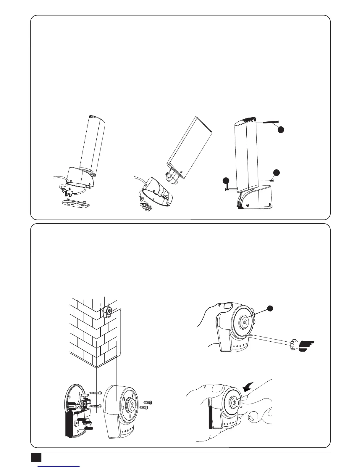
3.3.4 PKS-1 Key Selector
1). PKS-1 key selector is installed outside and close to the gate at the height of about 100cm, so that it could be used
by most people. Decide the installation position of PKS-1 first. See
Figure 3.3.4 (1)
.
2). Remove the round cover (A) by prizing it out with a screwdriver. See
Figure 3.3.4 (2)
.
3). Unscrew the two screws beside the lock body. See
Figure 3.3.4 (3)
.
4). Turn the key and separate the bottom of the shell with the lock body. See
Figure 3.3.4 (4)
.
Figure 3.3.4 (1)
Figure 3.3.4 (2)
A
Figure 3.3.4 (3)
Figure 3.3.4 (4)

 Loading...