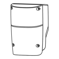
1. CONTROL BOX
CONTROL BOX INSTALLATION
1. Decide the installation position of control box first, it is suggested to be installed near the gate and should
be protected from possible damage. Be aware of the motor cable length before deciding the installation position.
2. Remove the cover by unscrewing the four screws on the cover. See Figure 1(1).
3. Use a screwdriver to puncture the holes beneath the bottom of the control box. See Figure 1(2).
4. Secure it on the wall. See Figure 1(3).
5. Wiring Connection:
Prepare all the wires of the accessories beforehand and connect the wires to the gear motors and accessories on
the PCB as shown in Figure 1(4). All of the wiring connections of the accessories are not requested to
distinguish the positive (+) and the negative (-) polarity.
1). Flashing Light: Connect the two wires from the flashing light to the terminal L+ and L- on the PCB.
2). Electric Latch: Connect the two wires from the electric latch to the terminal Lo + and Lo- on the PCB.
3). Gate openers: Refer to Figure 1(4) and connect the wires separately to the terminals on the PCB.
Motor 1: Connect the motor wire (White +) to the terminals Mo1 +, and (Yellow -) to the Mo1-.
Motor 2: Connect the motor wire (White +) to the terminals Mo2 +, and (Yellow -) to the Mo2 -.
Notes:
For gates opened outward,
Motor 1: Connect the motor wire (Yellow -) to the terminals Mo1 +, and (White +) to the terminals Mo1-.
Motor 2: Connect the motor wire (Yellow -) to the terminals Mo2 +, and (White +) to the terminals Mo2 -.
4). Photocells: See Figure 1(4)
(A) installed one set Photocell to FO1, SW3 setting as below:
3. Ph_conn1 > OFF and 4. Ph_conn2 > ON
(B) installed one set Photocell to FO2, SW3 setting as below:
3. Ph_conn1 > ON and 4. Ph_conn2 > OFF
(C) installed two sets Photocell, SW3 setting as below:
3. Ph_conn1 > OFF and 4. Ph_conn2 > OFF
(D) No Photocell has been installed, SW3 setting as below:
3. Ph_conn1 > ON and 4. Ph_conn2 > ON
1 2 3 4 5 6 7 8 9

 Loading...