3
PM 25MV v9 2021-12 Copyright © 2021 Quality Machine Tools, LLC
Section 1 INSTALLATION
THESE ARE THE MAIN POINTS TO WATCH OUT FOR!
But read the following pages for more information
• Handling the mill is at least a two-person job.
• Lower the center of gravity by hand-cranking the headstock down until the spindle nose
is just clear of the table.
• Lifting gear – sling, hoist or forklift – must be rated for at least 500 lb.
• Working location of the mill must allow: Full left-right travel of the table, and; Access to
the top of the column (for Z-axis leadscrew maintenance).
• Power requirement is 110V, 60Hz, 1φ, 20A circuit protection (spindle motor 14A full load).
• Extension cord not recommended; if no alternative, use 12 AWG not longer than 20 ft.
• Before connecting power for the rst time be sure that:
1. The machine is on a rm footing, adequately secured to bench or stand.
2. No chuck or collet is installed.
3. There are no clamps or locks on moving parts.
4. The speed control knob is set for the lowest speed.
1. Prepare the working location, bench or optional
stand.
Highly recommended!
Bolt the bench or stand rmly to the oor. Check
working clearances, Section 2.
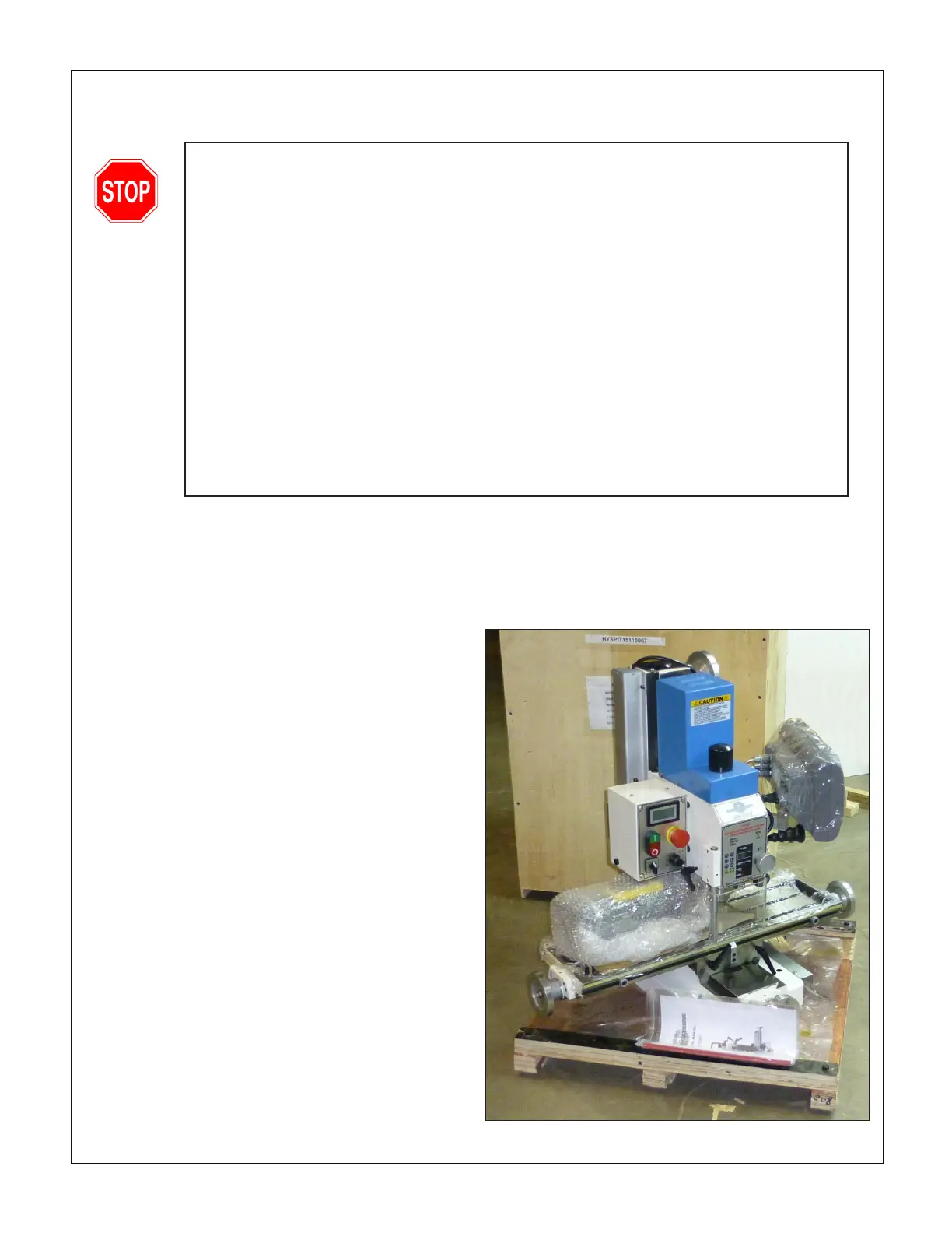
2. Remove the packing case from the pallet, Figure 1-1.
Unbolt the machine from the pallet. Install the largest
of the four handles on the headstock handwheel (top
of column on right). Install the three smaller handles
on the X-axis and Y-axis handwheels.
3. Release the Y and Z axis locks. Check that the mill’s
center of gravity is as far down and back as possible
by cranking both Y and Z handwheels.
4. Tape cloth padding to the underside of the tilt collar.
5. Run a sling under the padding, taking care not to
damage the Z-axis locking handle and the cooling
ns on the electrical box, Figure 1-2.
6. Hook the sling to the hoist. Slowly lift the mill, con-
trolling any tendency for it to swing as it clears the
pallet.
7. Roll the mill into position over the tray, then lower it
into place, Figure 1-3.
8. Secure the mill to the bench or stand. If this is a stand
Setting up the mill
The PM 25MV-BD is shipped in two packing cases, one for the machine and tray (and optional 3-axis DRO), one
for the stand, if ordered. The following procedure makes use of an engine hoist, minimum weight rating 500 lb.
Figure 1-1 Mill ready for lifting

 Loading...
