15
PM-30MV v3 2020-10 Copyright © 2020 Quality Machine Tools, LLC
Section 4 MAINTENANCE
Unplug the 220V power cord before any
maintenance operation!
RECOMMENDED LUBRICANTS
Ball oilers/oil cups (X and Y leadscrews): ISO 68 oil, such
as Mobil Vactra No. 2, or equivalent
X, Y and Z axis ways (dovetails): ISO 68 oil, Mobil Vactra
No. 2, or equivalent
Visible gears such as quill rack and pinion, Z-axis bevel
gears: light general purpose grease, NLGI No. 2, or equiva-
lent
X and Y leadscrews: ISO 68 oil, Vactra No. 2, or equivalent
Z leadscrew: ISO 68 oil or NLGI No. 2 grease
GENERAL OILING
Assuming a clean environment – no abrasive particles or ma-
chining debris – lack of proper lubrication is the main cause
of premature wear. Rotating parts are easy to lubricate, slid-
ing parts are not. Gibs are tightened for the best compromise
between rigidity and slideability, which means practically zero
gap between the ways. Take time to understand exactly which
are the bearing surfaces on the various dovetail surfaces; this
is not obvious – some of the interfaces look like bearing surfac-
es, but are simply narrow gaps.
Every few hours of operation:
1. Apply the recommended way-oil with a dedicated
short-bristle brush such as the type used for applying
ux.
2. Use a similar brush to apply oil or grease to the
leadscrews.
3. Apply oil to ball oilers/and or oil cups, see below.
Ball oilers
Use a pump-type oil can with tip large enough to more than
span the oiler’s spring-loaded steel ball. Oil pressure will dis-
place the ball, allowing oil to ow, provided the oil can tip is
rmly pressed onto the brass seating. Before oiling check that
the ball is not stuck – press it lightly with a probe.
Quill rack and pinion
Lower and lock the quill. Using a sti ux brush, clean the vis-
ible portions of the rack and pinion. Raise and lower the quill
to expose the remainder of the working surfaces, locking and
cleaning at each setting.
Spindle bearings
See Servicing Quill and Spindle, two pages on.
Remove all machining debris and foreign
objects before lubricating ANYTHING! If need
be, any oil is better than no oil – but use the
recommended lubricants when you can.
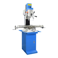
GIB ADJUSTMENT
Gibs on the X, Y and Z axes control the t of the mating dove-
tailed surfaces. They are gently-tapered lengths of ground cast
iron located by opposing screws at each end. Adjusting them
is a trial and error process that takes time and patience. Aim
for the best compromise of rigidity and reasonably free table
movement. Too tight means accelerated wear on the ways and
leadscrews. Too free means workpiece instability, inaccuracies
and chatter.
Both screw heads must be tight against the gib ends. If you
loosen one, tighten the other. Remove the way covers for ac-
cess to the back of the Y gib and bottom of the Z gib.
Figure 4-1 Gib adjustment, X and Y axes (representative)
The back adjustment screw for the Y axis gib is under the solid rub-
ber way cover behind the table. The left adjustment screw for the X
axis is in a similar location on the left side of the saddle casting.
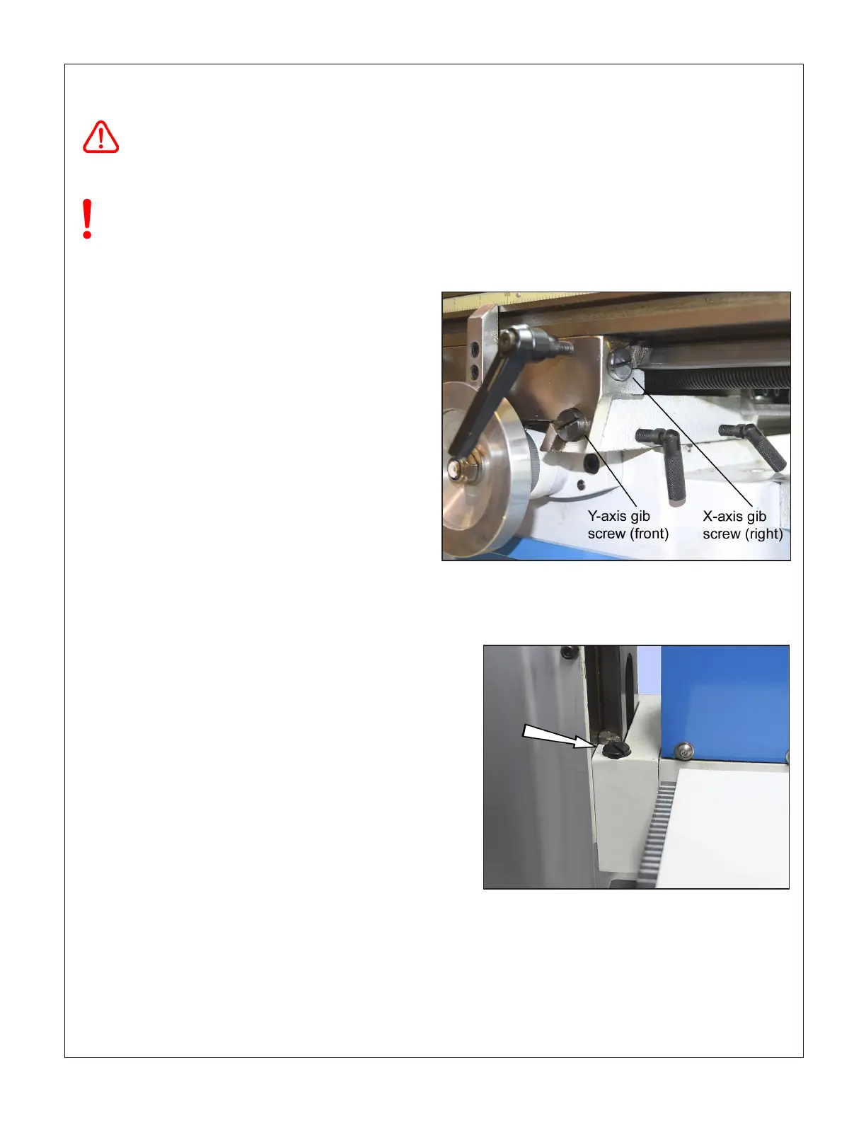
Figure 4-2 Z-axis gib adjustment, upper screw
The lower screw is under the pleated way cover.
 Loading...

