9
PM-30MV v3 2020-10 Copyright © 2020 Quality Machine Tools, LLC
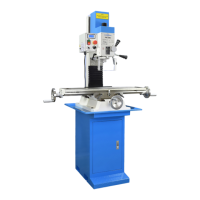
Two tools are required to install or remove R8 tooling: a 12 mm
wrench for the square drawbar nut, and the supplied C-wrench
to engage the ats at the bottom end of the spindle.
Install tooling
Install the R-8 device, then hand-thread the drawbar into it until
the shoulder on the drawbar bottoms on the spindle cap, Fig-
ure 3-4). Lock the spindle with the C-wrench while at the same
fully tightening the drawbar with the 12 mm wrench. [Do NOT
try to lock the spindle using the ats on the drawbar cap; this is
screwed onto the spindle to secure a retaining clip above the
return spring cup.]
Figure 3-4 Two-step belt drive
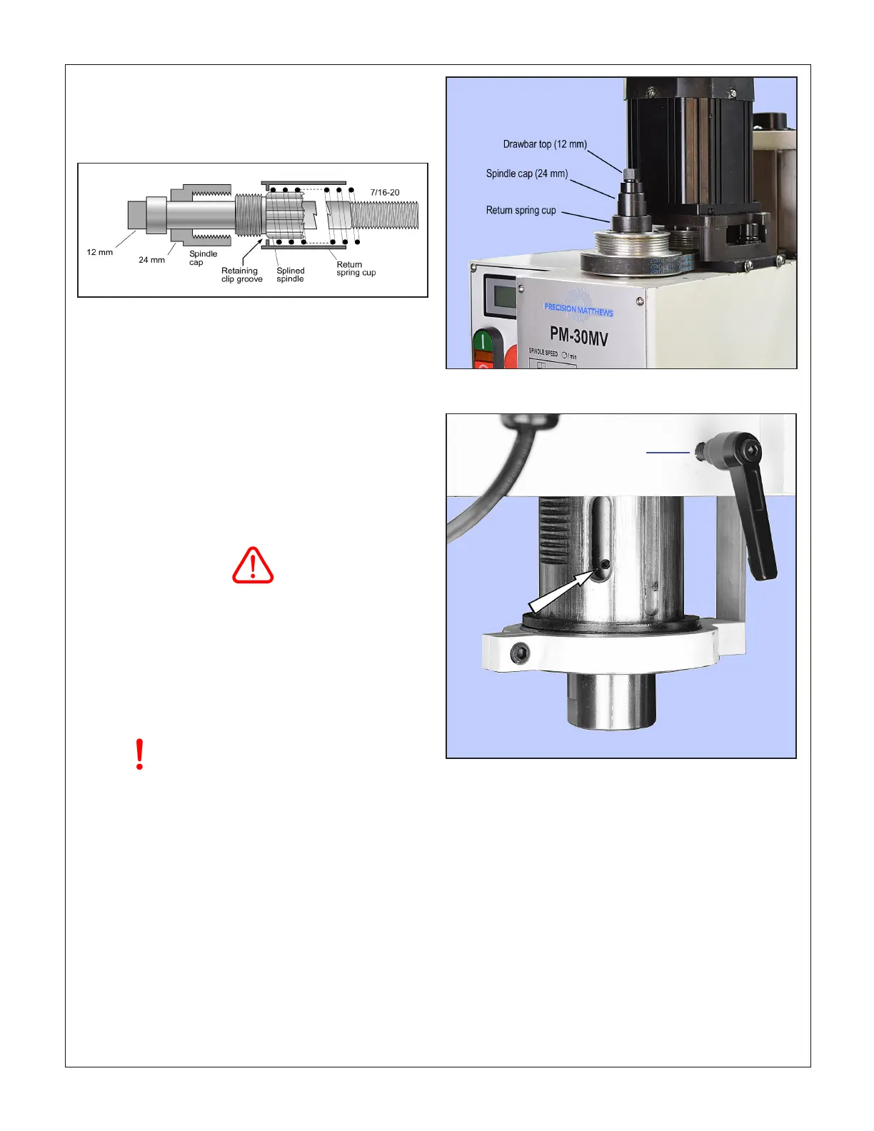
Figure 3-5 Collet set screw
Remove tooling
Protect the table, vise or workpiece under the spindle with rags
or scrap wood. Why? Because they can easily be damaged by
falling tools and drill chucks. The cutting tool itself can also be
damaged in the same way.
Lock the spindle with the C-wrench, loosen the drawbar one
half turn or less, just enough to unseat the taper, then tap the
top of the drawbar with a brass or dead-blow hammer to free
the device. Unscrew the drawbar with one hand while support-
ing the R-8 device with the other hand.
R8 tooling is located in the spindle bore by a set screw. If
it is dicult or impossible to insert the R8 device, chances
are the set screw is in too far. Rotate the spindle by hand
to expose the screw, Figure 3-5, then back it out a fraction
of a turn using a 2.5 mm hex key.
Hand rotate the spindle again to check that the screw
clears the inside surface of the quill.
INSTALLING AND REMOVING TOOLING
The spindle and drawbar are designed for R-8 taper collets,
drill chucks and other arbors with the standard 7/16”-20 inter-
nal thread.
Except for maintenance purposes,
do not remove the spindle cap
MOVING THE TABLE
Conventionally, left-right movement of the table is said to be
along the X-axis (also called “longitudinal travel” or “travers-
ing”). Front-back movement is on the Y-axis, sometimes called
“cross travel”.
Each axis has a leadscrew with handwheel and graduat-
ed dial with 0.001” divisions, 0.1” per revolution. If the mill is
not equipped with digital readouts (DROs), the table can be
accurately positioned by counting whole turns and divisions,
keeping leadscrew backlash in mind. This means that table
motion must always be in the same direction up to the point of
reference, then on to the desired location, see “Positioning by
Counting X-Y Divisions”, later in this section.
Figure 3-3 Drawbar & spindle schematic
Quill lock
 Loading...

